![]()
Coreform Cubit 2025.8 User Documentation
![]()
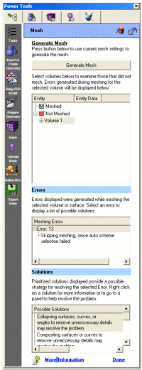
The mesh generation panel in ITEM is different from the other panels in Coreform Cubit. Meshing errors can arise from a number of different problems. Many of these problems are caused from improper geometry preparation/cleanup. Other problems can be caused from improper interval settings, or meshing schemes. Instead of suggesting specific operations as it does on other panels, the meshing panel in ITEM will suggest several possible solutions based on the error message output. Each of these solutions may require significant user input, and may require you to revisit previous ITEM panels or Control panels. To open the appropriate Control panel, you can right click on the solution and select "Show Command Panel". For convenience, these general solutions are described here, including which ITEM panels and which Control panels they refer to. References to help topics are also included.

Figure 1. ITEM Mesh Panel
Diagnostic: This solution message appears when auto scheme selection fails. There are many reasons that auto scheme selection may have failed. Check to make sure that your volume is broken up into meshable parts. For sweepable volumes, this means that each volume should only have one target surface.
Action: Right-clicking on this solution and selecting the "Show command panel" option will open the webcutting commands on the control panel. Alternatively, you can also return to the ITEM decomposition panel for more webcutting suggestions.
Help Topics:Diagnostic: This solution message appears when auto scheme selection fails, interval matching fails, or interval assignments fail. Setting the schemes manually may help resolve some of these issues. It may also help to set source and target surfaces explicitly for swept meshes.
Action: The volume schemes can be set explicitly from the Volume-Mesh control panel. The "Set Source and Target" panel in ITEM can be used to aid in setting explicit source and target surfaces for swept meshes.
Help Topics:Diagnostic: This solution message appears for many reasons: auto scheme selection fails, interval matching fails, interval assignments fail, inconsistent edge-face ratios, odd number of intervals on a paver loop, or connectivity problems. Setting explicit intervals may be necessary
Action: The volume mesh intervals can be set explicitly from the Volume-Interval control panel. The "Set Element Sizes" panel in ITEM can be used to aid in setting explicit sizes and sizing functions for meshes.
Help Topics:Diagnostic: This solution message appears when auto-scheme selection fails. A model may contain small curves or surfaces that need to be composited with adjacent surfaces. Or it may just contain more detail than is needed for analysis. Compositing surfaces and curves does not affect the underlying geometry.
Action: The Remove Small Features or Force Sweep Topology panels in ITEM may suggest several possible candidates for compositing. The Surface-Modify-Composite or the Curve-Modify-Composite panels can be used to composite surfaces or curves respectively. These panels are also used to delete virtual geometry from curves or surfaces.
Help Topics:Removing Small and Narrow Features describes using ITEM to remove small and narrow features in your model.
Forced Sweepability describes using ITEM to force sweepability using virtual geometry.
Composite Curves explains how to composite curves in Coreform Cubit.
Composite Surfaces explains how to composite surfaces in Coreform Cubit.
Decomposition Tutorial Example 7 has an example of using composite curves to improve meshability.
Power Tools Tutorial has another example of using composite geometry.
Diagnostic: This solution message appears when auto-scheme selection fails. Collapsing a surface involves splitting a surface, and compositing it with adjacent surfaces.
Action: The Remove Small Features panel in ITEM may suggest several possible candidates for collapse. The Surface-Modify-Collapse, Curve-Modify-Collapse, or Vertex-Modify-Collapse Angle panels can also be used to collapse surfaces, curves, or angles respectively.
Help Topics:Diagnostic: This solution message appears when auto-scheme selection fails. Removing unnecessary surfaces may improve meshability.
Action: The Remove Small Features panel in ITEM may suggest several possible candidates for removal. The Surface-Modify-Tweak panel, Surface-Modify-Remove panel, Curve-Modify-Tweak or the Volume-Modify-Remove Slivers panels are also used to remove unnecessary features in a model.
Help Topics:Diagnostic: This solution message appears when mesh generation creates poor quality elements, particularly if it creates inverted or "negative Jacobian" elements. In some cases, smoothing a mesh may get rid of these bad elements.
Action: Depending on the geometry type, the smoothing panel can be accessed from the Control panel under Volume-Smooth or Surface-Smooth panels. It is also helpful to use the Validate Mesh page in ITEM for assessing quality metrics.
Help Topics:Diagnostic: This solution message appears when mesh generation creates a poor quality mesh, due to negative Jacobians, inconsistent edge-face ratios, connectivity problems, or any other invalid mesh configuration. Mesh generation can be a very iterative process. It is sometimes necessary to delete a mesh and try different schemes, sizes, or even just change the meshing order. Sometimes you must further decompose or modify your geometry to get it to mesh.
Action: To delete a mesh, you can select it in the graphics window and choose Delete Mesh from the right-click context menu. You can also delete a mesh from any of the Mesh-Entity-Delete panels on the Control Panel.
Help Topics:Diagnostic: This solution message appears when mesh generation fails to assign valid vertex types on mapped or submapped surfaces.
Action:To change the vertex type on a surface, select the Surface-Mesh-Submap-Advanced or Surface-Mesh-Map-Advanced panels. From here you can assign and view vertex types.
Help Topics: