CAPABILITIES
ISOGEOMETRIC ANALYSIS (IGA)
Streamline Simulation with Efficient, Accurate Meshes
Isogeometric Analysis (IGA) streamlines simulation processes by automatically generating high-quality meshes for complex geometries without manual adjustments, significantly reducing preprocessing time.
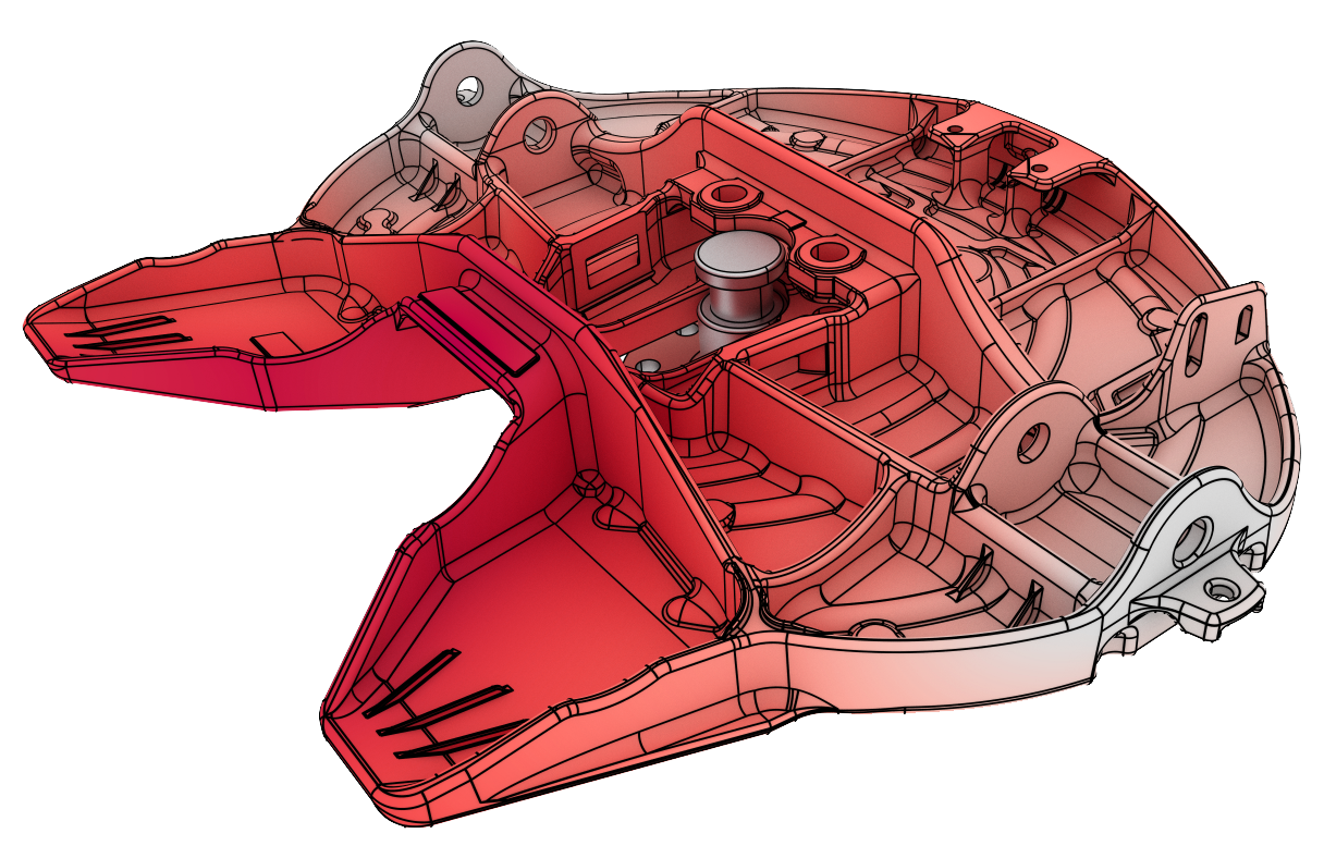
Overview
Isogeometric analysis (IGA) allows you to build quality meshes with little to no user input, and use them in highly efficient and highly accurate simulations. Isogeometric analysis doesn’t require you to fit meshes to complex geometry and eliminates the need to defeature a model. This allows you to achieve more accurate simulation results and compute efficiency of the simulation, while reducing or eliminating the time required to generate the mesh. IGA is available for commercial use in the Coreform Flex Preprocessor and Solver.
Isogeometric analysis doesn’t require you to fit meshes to complex geometry and eliminates the need to defeature a model.
Coreform Advantage
Model setup
Coreform Flex provides a flexible environment for importing and working with CAD models from a wide variety of formats. It has strong interoperability with many CAD systems, making it easier to run simulations on complex models. Coreform U-splines and isogeometric analysis (IGA) technology allow for seamless integration between CAD and meshing, avoiding the need for tedious geometry cleanups often associated with traditional FEA workflows. Coreform’s ability to handle imperfect or “dirty” geometries reduces the need for manual preparation or cleaning of imported models, saving significant time during the setup phase.
Automation and scripting
Coreform Flex includes robust Python scripting support. Users can automate repetitive tasks like mesh generation, boundary condition assignment, and analysis setup, which greatly enhances productivity on large projects or for repetitive operations. The scripting environment allows for custom workflows, macro creation, and batch processing, which is particularly useful for building parametric meshes or task optimization. Coreform’s scripting capabilities make it easy to integrate with other software tools or simulation environments, providing a versatile and automated simulation pipeline.
Mesh support
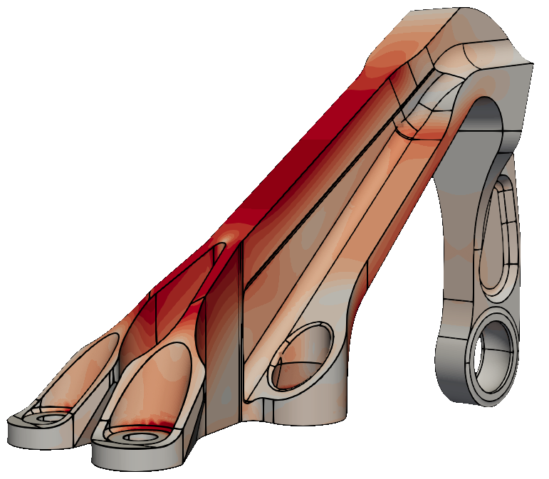
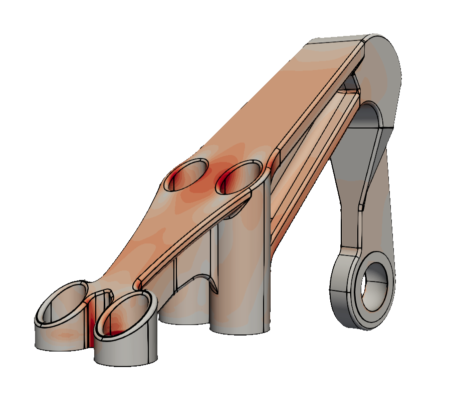
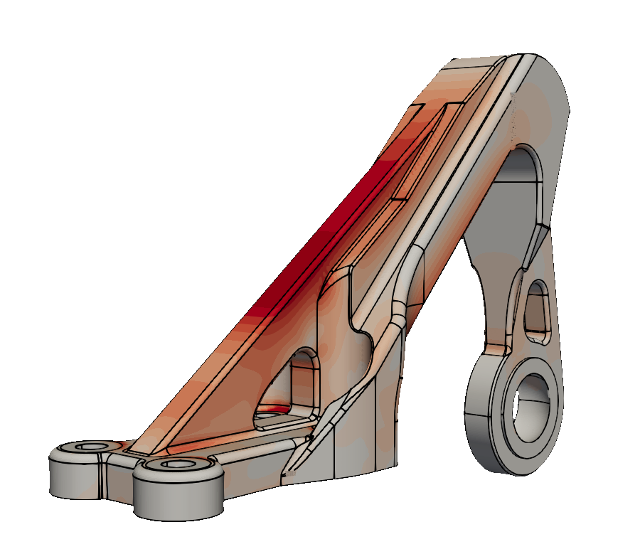
Coreform’s proprietary U-splines technology allows for higher-order elements and smooth representations of geometry, making it easier to generate more accurate meshes with fewer elements. Traditional FEA workflows often require tedious meshing processes, while Coreform’s IGA approach generates meshes that utilize the CAD geometry. This eliminates inconsistencies in mesh simplification and allows for better element quality.
Broad range of physics
Coreform Flex is built to support a full range of physics, including linear and non-linear static and dynamic simulations, contact, modal analysis, and more. See the current capabilities in our reference manual.
IGA vs. traditional FEA
What’s wrong with traditional meshing?
Traditional meshing for simulations of real-world engineering problems requires a balance between three competing capabilities: accuracy of the simulation results, compute efficiency of the simulation, and the time required to generate the mesh. Generally, engineers can choose any two of these options but not all three. In practice, they must introduce approximations and assumptions that limit the usefulness of simulation in their engineering workflows.”
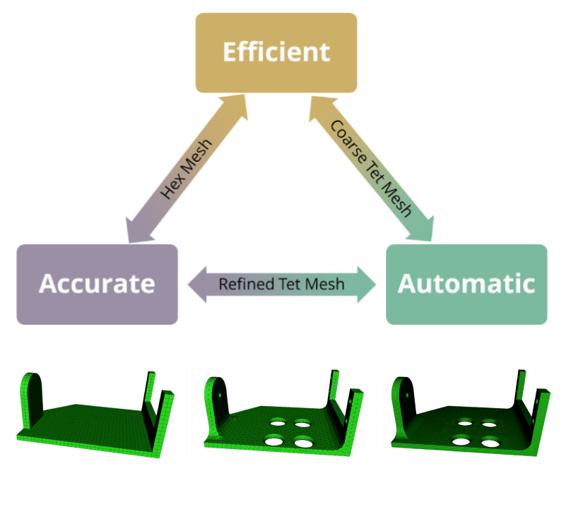
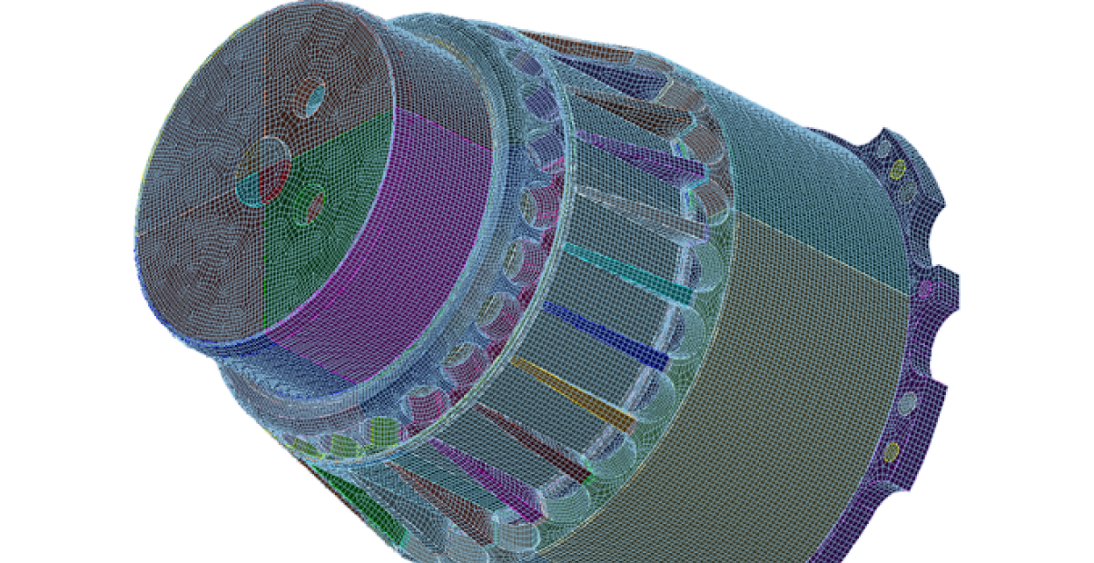
Many nonlinear analyses all but require quality hexahedral meshing. In these cases, the engineer must perform manual mesh generation steps, including:
- Defeaturing the model to permit a hex-mesh
- Partitioning of the geometry by the engineer into hex-meshable regions
- Defeaturing the model to simplify the partitioning process
- Manipulating the mesh to correct invalid hex-meshes.
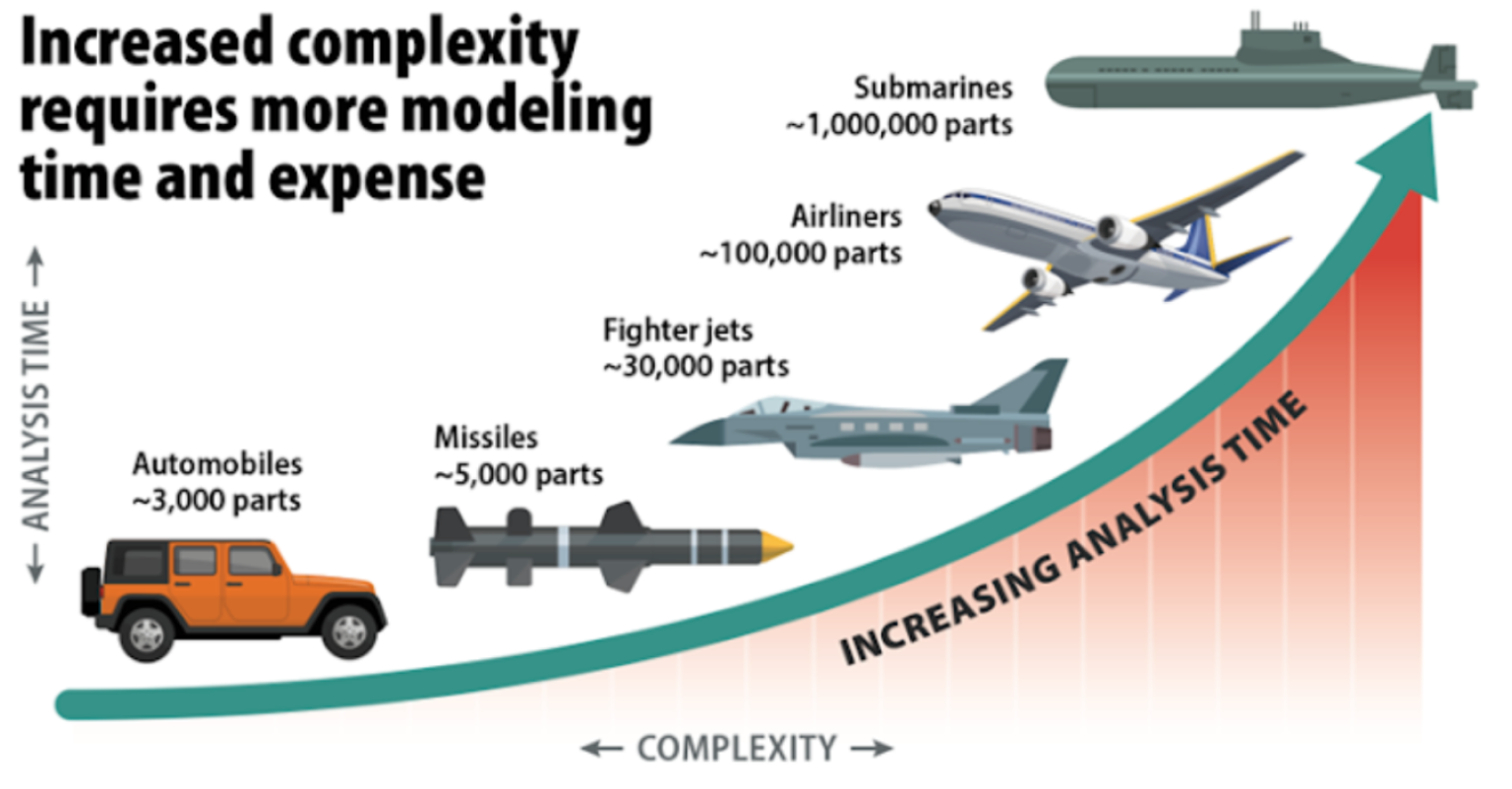
Mesh generation is a time and labor-intensive process that provides no value to the eventual customer of the engineering analysis, but is simply required by the nature of hexahedral elements. As products become more complex, and as CAD advances to capture more details of geometry, this becomes even more expensive. Many product teams can’t afford to perform these analyses on their products at all.
IGA Fundamentals
IGA was introduced by Dr. Thomas J.R. Hughes in 2005, and has since captured the imagination of researchers and engineers across the globe. The fundamental idea of IGA is to use the same geometry for both design and simulation. Traditional FEA requires Lagrange bases, which are generally faceted approximations of the CAD, while traditional CAD leverages smooth spline functions. Hughes showed that these smooth splines actually make a very robust and superior basis for simulation. Over 4000 papers have been published since then showing these benefits.
In traditional CAD, solids are actually not solid. Instead, they are a set of manifold surfaces that bound the solid. For example, the left image shows the surfaces that bound the solid. The middle image shows the extraneous pieces of each surface trimmed away to create a closed collection of manifold surfaces. The right image shows the single, closed-solid object displayed to the user.
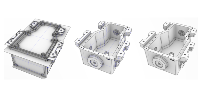
Since true solids or solids with a true three-dimensional parameterization are not available in CAD, mesh generation schemes have been created to “fill in” the solid so FEA can occur. This process has many well-known issues and is the central cause of the varied bottlenecks that occur when moving a CAD model into simulation.
What sets Coreform IGA apart
Coreform enables virtual prototyping across many industries at a much higher speed, lower cost, with superior accuracy and robustness than anything else on the market today. This allows companies to bring complex, expensive, engineered products to market significantly faster. Because our solution allows for quick virtual prototyping, improved product design and innovation is more feasible. We leverage a novel trimming procedure to automatically produce simulation models from CAD geometry of any complexity.

Coreform’s trimmed spline capability is the first spline representation that makes the IGA vision of performing complex, linear and non-linear FEA directly on CAD a reality. The trimming procedure utilizes higher-order degree and smooth spline functions. We leverage those spline functions during the simulation to produce results that are more accurate and are more robust than traditional FEA approaches with respect to large deformation, different dynamic regimes (both fast and slow dynamics), and contact/impact events. Coreform is the first to achieve this.
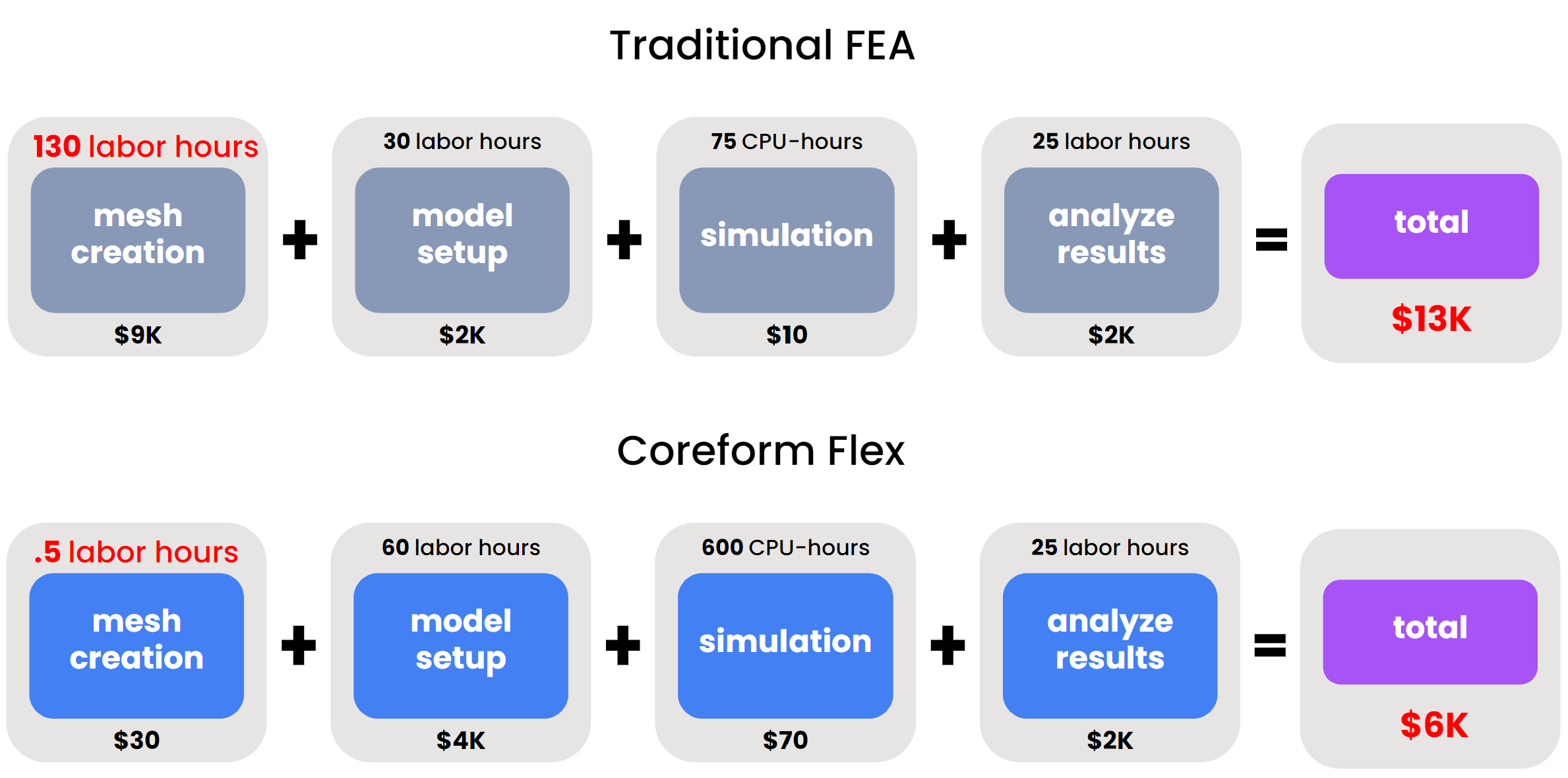
Our new trimming extends traditional surface-based CAD technology by providing tools to automatically create a solid with a three-dimensional parameterization for any CAD object composed of just surfaces. Leveraging this new approach, all traditional mesh generation techniques are eliminated, and all the advanced simulation technologies available in IGA can be brought to bear directly on this representation.
Coreform reports are authored by Coreform technical staff often in collaboration with other researchers and students. They are meant to provide interested parties with an in-depth treatment of the technical foundations of spline-based simulation.
See why Coreform Cubit is trusted by government and industry leaders around the world
From nuclear energy to automotive, Coreform Cubit’s performance and capabilities consistently deliver.
Courtesy Sandia National Labs
