Coreform DAGMC Model Preparation and Export Tutorial
About this tutorial
In this tutorial we will learn to prepare models for application in particle transport codes with the Direct Accelerated Monte Carlo (DAGMC) toolkit. To start, we’ll model a simple PWR fuel pin composed of three concentric cylinders representing the fuel pin, gap, and cladding and with a surrounding rectangular prism (brick) containing a water moderator. We’ll then look at a more complex example: a tokamak reactor.
PWR Fuel Pin
Creating the geometry
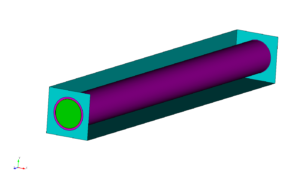
To begin, we’ll create the three cylinders with radii 0.39 cm, 0.4 cm, and 0.45 cm for the outer radii fuel pin, gap, and cladding respectively. The prism for the water moderator will have a width of 1.26 cm. True fuel pins are typically 120-200 cm in length, but we’ll model a 10 cm pin in this tutorial for clear visualization.
import os
import sys
path_to_cubit = "/home/gvernon2/cubit/build_lin64/bin/Release"
sys.path.append( path_to_cubit )
import cubit
cubit.init( ['cubit', '-driver', 'offscreen', "-noecho", "-nojournal" ] )
cubit.cmd( "reset" )
cubit.cmd( "create cylinder radius 0.39 height 10" )
cubit.cmd( "create cylinder radius 0.4 height 10" )
cubit.cmd( "create cylinder radius 0.45 height 10" )
cubit.cmd( "create brick x 1.26 y 1.26 z 10" )

cubit.cmd( "remove overlap volume 3 4 modify volume 4" )
cubit.cmd( "remove overlap volume 2 3 modify volume 3" )
cubit.cmd( "remove overlap volume 1 2 modify volume 2" )
cubit.cmd( "merge all" )

cubit.cmd( "compress ids" )
...deleting 7071 tris from database...
...deleting 10379 edges from database...
...deleting 3323 nodes from database...
Successfully created cylinder volume 1
Successfully created cylinder volume 2
Successfully created cylinder volume 3
Successfully created brick volume 4
Created volume(s): 5
Updated volume(s): 4
Destroyed volume(s): 5
Created volume(s): 6
Updated volume(s): 3
Destroyed volume(s): 6
Created volume(s): 7
Updated volume(s): 2
Destroyed volume(s): 7

...Merging all features in the model

...Merging all Surfaces in the model
Comparing Surfaces:
Comparing 18 Surfaces for Merge
0   |    |    |    |    50   |    |    |    |  100
**************************************************
Consolidated 3 pairs of surfaces

...Merging all Curves in the model
Consolidated 0 curves

...Merging all Vertices in the model
Consolidated 0 pairs of vertices
All detected matches successfully merged

This model contains the geometry as described above with the appropriate volumes subtracted from one another to produce the fuel, gap, cladding, and moderator regions. Our task will be to prepare the geometry for export by ensuring that the faces of coincident volumes are shared (merged), mesh the model, and that the appropriate material and boundary conditions have been applied.
Checking the geometry
In order to move particles robustly from volume to volume, DAGMC requires that coincident volumes share surfaces. DAGMC leverages this topological information in the resulting triangle mesh file to change the particle’s logical containment from one volume to the other when a particle crosses the triangle of a shared surface.
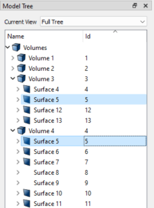
By examining the model tree (see below image), we can see that adjacent volumes do in fact share surfaces. In the image of the tree, we see that volume 4 (cyan) shares surface 5 with volume 3 (pink). By nature of the final volumes in this model resulting from subtractions of other volumes, this topological consistency is guaranteed. This is not always the case, however, and as we will see later in the tutorial we may need to imprint prior to merging the model before moving on to metadata.
Assigning Materials and Boundary Conditions
A DAGMC model requires that all volumes have a material assignment, including void regions. To assign a material in Cubit we will create a block for each material in the model. Blocks can be created and the surface mesh of a volume assigned to the block with the following commands
create block 1
block 1 add volume 1
And a material can be created and added to this block with the following
create material 1 name "fuel"
block 1 material "fuel"
The block creation and volume assignment can be combined into one command as well
block 1 volume 1
Now we’ll repeat this for volumes 2, 3, and 5 with the material names vacuum, clad, moderator respectively.
cubit.cmd( "create block 1" )
cubit.cmd( "block 1 add volume 1" )
cubit.cmd( "create block 2" )
cubit.cmd( "block 2 add volume 2" )
cubit.cmd( "create block 3" )
cubit.cmd( "block 3 add volume 3" )
cubit.cmd( "create block 4" )
cubit.cmd( "block 4 add volume 4" )

cubit.cmd( "create material 1 name 'fuel'" )
cubit.cmd( "create material 2 name 'vacuum'" )
cubit.cmd( "create material 3 name 'clad'" )
cubit.cmd( "create material 4 name 'moderator'" )

cubit.cmd( "block 1 material 'fuel'" )
cubit.cmd( "block 2 material 'vacuum'" )
cubit.cmd( "block 3 material 'clad'" )
cubit.cmd( "block 4 material 'moderator'" )
Added Volume 1 to block 1
Added Volume 2 to block 2
Added Volume 3 to block 3
Added Volume 4 to block 4


Created material 1.
Created material 2.
Created material 3.
Created material 4.
For this simple model, that’s all there is to material assignments. Now on to boundary conditions. The method for implementing boundary conditions is dependent on the Monte Carlo code the model will be used with. DAGMC models sometimes have a “graveyard” volume surrounding all other volumes to capture and terminate all particles that reach it. We’ll be building this model for use with OpenMC, which allows us to apply boundary conditions directly to surfaces rather than create a non-physical volume.
create sideset 1
sideset 1 name 'boundary:reflecting'

sideset 1 add surface 2 3 10 11 12 13 14 15
sideset 1 add surface 6 7 8 9
To model an infinite sea of pincells, we’ll apply reflecting boundary conditions to all exterior surfaces of the model. This will be modeled as an infinite sea of pincells in the Monte Carlo code allowing us to compute what is known as “K-inf” — the neutron multiplication factor without particle leakage due to geometry boundaries.
More details on code-specific steps for creating DAGMC models can be found here.
cubit.cmd( "create sideset 1" )
cubit.cmd( "sideset 1 name 'boundary:reflecting" )
cubit.cmd( "sideset 1 add surface 2 3 10 11 12 13 14 15" )
cubit.cmd( "sideset 1 add surface 6 7 8 9" )
Set name of sideset 1 to "boundary:reflecting"
Added Surface 2 to sideset 1
Added Surface 3 to sideset 1
Added Surface 10 to sideset 1
Added Surface 11 to sideset 1
Added Surface 12 to sideset 1
Added Surface 13 to sideset 1
Added Surface 14 to sideset 1
Added Surface 15 to sideset 1
Added Surface 6 to sideset 1
Added Surface 7 to sideset 1
Added Surface 8 to sideset 1
Added Surface 9 to sideset 1
Meshing the Model
Now that we’re sure the geometry is correct and we’ve assigned our boundary conditions, we can mesh the model. We’ll use the new coarse mesh settings in the surface trimesher to do so.
- Select
Mesh->Surface->Mesh->Trimeshin the command panel
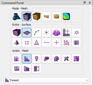
- Then enter
allinto theSelect Surfacespickwidget and check the box next toCoarse Mesh Settings
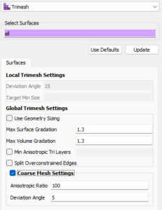
cubit.cmd( "set trimesher coarse on ratio 100 angle 5" )
cubit.cmd( "surface all scheme trimesh" )
cubit.cmd( "mesh surface all" )
Calculating Auto Size
0   |    |    |    |    50   |    |    |    |  100
**************************************************
Matching intervals successful.
Begin tri meshing 15 surfaces 1 to 15
Meshing surfaces
0   |    |    |    |    50   |    |    |    |  100
*************************************************
Completed tri meshing 15 surfaces with 847 tris
Surfaces 1 to 15 meshing completed using scheme: trimesh
Generated 847 tris
cubit.cmd( "surf all visibility on")
cubit.cmd( f"hardcopy '{os.path.join( os.getcwd(), 'images', 'pwr_mesh_overview.png' )}' png window 2" )
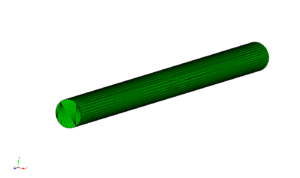
cubit.cmd( "draw vol 1" )
cubit.cmd( f"hardcopy '{os.path.join( os.getcwd(), 'images', 'pwr_mesh_fuel.png' )}' png window 2" )
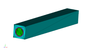
- Finally, click the
Meshbutton. The resulting mesh should look similar to the mesh in the images below.
Exporting the Model
Finally, we’ll export the DAGMC model. To do so, select File -> Export... in the file menu, then select the DAGMC (*.h5m) filetype, and then enter the file name you’d like to use.
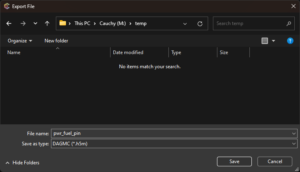
This can also be accomplished using the dagmc filetype in the export command:
export dagmc "pwr_fuel_pin.h5m"
The resulting file can now be applied in a particle transport simulation using DAGMC geometry.
cubit.cmd( "export dagmc 'pwr_fuel_pin.h5m' overwrite" )
Found 14 entities of dimension 0
Found 18 entities of dimension 1
Found 15 entities of dimension 2
Found 4 entities of dimension 3
Tokamak model
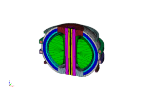
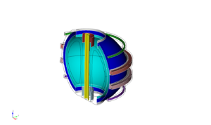
In this section, we’ll look at a tokamak model generated using the Paramak tool for tokamak design. This model contains higher order surfaces that may be challenging to otherwise model using the native constructive solid geometry (CSG) engines provided by most particle transport codes.
Select File -> Open and choose the tokamak_w_mats.cub5 file provided below.
cubit.cmd( "reset" )
cubit.cmd( "open './files/tokamak.cub5'" )
...deleting 847 tris from database...
...deleting 1161 edges from database...
...deleting 316 nodes from database...
Geometry engine set to: ACIS Version 33.0.0.0
Geometry engine set to: ACIS Version 33.0.0.0
Read 16 ACIS Entities from the input file
Progress
Processing 16 ACIS Entities
0   |    |    |    |    50   |    |    |    |  100
**************************************************

Progress
Building 16 CUBIT Entities
0   |    |    |    |    50   |    |    |    |  100
**************************************************

Constructed 16 Volumes: 1 to 16
WARNING: 16 invalid names were found during import.

Geometry engine set to: ACIS Version 33.0.0.0
Successfully opened CUBIT file './files/tokamak.cub5'
cubit.cmd( "graphics perspective off" )
cubit.cmd( "graphics parallel scale  796.92089" )
cubit.cmd( "from  1420.9563 -3228.8524   1668.639" )
cubit.cmd( "at   -92.083092  311.58432 -42.365141" )
cubit.cmd( "up   -0.15198041  0.37666499  0.91379727" )

cubit.cmd( f"hardcopy '{os.path.join( os.getcwd(), 'images', 'tokamak_geometry_overview.png' )}' png window 2" )
The following model should appear:
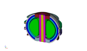
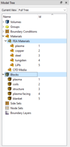
Materials have already been added to this model, so we don’t need to repeat that process:
Imprinting and merging
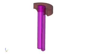
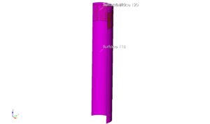
This model does need some additional work, however. Let’s take a closer look at the surfaces of volumes 3 and 7.
draw vol 3 7
graphics mode transparent
cubit.cmd( "draw vol 3 7" )
cubit.cmd( "graphics mode transparent" )
cubit.cmd( "from  3190.5998    -2173.531  1818.3984" )
cubit.cmd( "at    -345.81134   264.83695  161.32015" )
cubit.cmd( "up    -0.30323586  0.19420683 0.93291571" )
cubit.cmd( "zoom reset" )
cubit.cmd( f"hardcopy '{os.path.join( os.getcwd(), 'images', 'tokamak_geometry_vol_3_7_detail.png' )}' png window 2" )
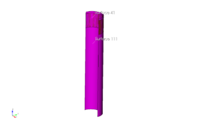
The model tree shows that these two do not share surfaces. Without imprinting and merging, particles will exit volume 3 (purple) crossing surface 41 and enter a space between volumes known as the implicit complement before entering volume 7 through surface 111. The implicit complement is a logical volume built by DAGMC that occupies all undefined space in the CAD model. In artistic terms it is the “negative” of the CAD bodies. Because the implicit complement is based purely on the topology of the model and surfaces 41 and 111 only have a volume on one side according to the topology, the implicit complement occupies the logical space between these surfaces.
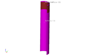
cubit.cmd( "graphics mode smoothshade" )
cubit.cmd( "draw surface 41 111" )
cubit.cmd( "locate surface 41 111")
cubit.cmd( f"hardcopy '{os.path.join( os.getcwd(), 'images', 'tokamak_geometry_vol_3_7_surface_detail.png' )}' png window 2" )
To build a robust DAGMC model, we’ll need to imprint and merge these surfaces. This will result in a single, shared surface between volumes 3 and 7 where they meet. The model topology in the DAGMC file will indicate that volume 3 is on one side of this surface and volume 7 on the other. This will allow particles to pass between the volumes efficiently and robustly during simulation without entering the implicit complement.
First, we’ll tackle imprinting and merging the surfaces. To imprint the model, we will run
imprint volume 3 7
cubit.cmd( "imprint volume 3 7" )
Group imprint finished.
Updated volume(s): 3
IMPRINT completed.
cubit.cmd( "display" )
cubit.cmd( "draw surface 41 118 119 120" )
cubit.cmd( "zoom reset" )
cubit.cmd( "locate surface 41 118 119 120" )
cubit.cmd( f"hardcopy '{os.path.join( os.getcwd(), 'images', 'tokamak_geometry_vol_3_7_surface_imprint_detail.png' )}' png window 2" )
The imprint command creates new surfaces. If we locate the new surfaces in volume 3 we see that one of its new surfaces,surface 119, corresponds to surface 41 of volume 7.
Surfaces 119 and 41 are still separate surfaces, however. Were we to mesh and export a DAGMC model at this point, particles would still move from volume 3 to volume 7 through the implicit complement. To create a single, shared surface we’ll merge the surfaces of volumes 3 and 7:
merge volume 3 7
cubit.cmd( "merge volume 3 7" )
Comparing Surfaces:
Comparing 14 Surfaces for Merge
0   |    |    |    |    50   |    |    |    |  100
**************************************************
Consolidated 1 pair of surfaces
Comparing Curves:
Comparing 30 Curves for Merge
0   |    |    |    |    50   |    |    |    |  100
**************************************************
Consolidated 0 pair of curves
Consolidated 0 pairs of vertices
cubit.cmd( "display" )
cubit.cmd( "draw surface 118 120 41" )
cubit.cmd( "zoom reset" )
cubit.cmd( "locate surface 118 120 41" )
cubit.cmd( f"hardcopy '{os.path.join( os.getcwd(), 'images', 'tokamak_geometry_vol_3_7_surface_imprint_merge_detail.png' )}' png window 2" )
Once this step is complete surface 42 is now present in both volumes.
To create a fully robust model we’ll perform this operation for the entire model with the following commands
imprint all
merge all
cubit.cmd( "imprint all" )
cubit.cmd( "merge all" )
Imprinting 16 ACIS Bodies
0   |    |    |    |    50   |    |    |    |  100
**************************************************
Group imprint finished.
Updated volume(s): 3, 7, 8, 14, 15
IMPRINT completed.

...Merging all features in the model

...Merging all Surfaces in the model
Comparing Surfaces:
Comparing 128 Surfaces for Merge
0   |    |    |    |    50   |    |    |    |  100
**************************************************
Consolidated 32 pairs of surfaces

...Merging all Curves in the model
Comparing Curves:
Comparing 183 Curves for Merge
0   |    |    |    |    50   |    |    |    |  100
**************************************************
Consolidated 0 pair of curves

...Merging all Vertices in the model
Consolidated 0 pairs of vertices
All detected matches successfully merged
cubit.cmd( "display" )
cubit.cmd( "draw surf all with is_merged" )
cubit.cmd( "draw curve all add" )
cubit.cmd( "color curve all black" )
cubit.cmd( "color curve all in surface with is_merged white" )
cubit.cmd( "zoom reset" )
cubit.cmd( f"hardcopy '{os.path.join( os.getcwd(), 'images', 'tokamak_geometry_merged_surfaces.png' )}' png window 2" )
Now that this is complete we can mesh the model as before and export a DAGMC file
set trimesher coarse on ratio 100 angle 5
surface all scheme trimesh
mesh surface all

export dagmc "paramak.h5m"
cubit.cmd( "set trimesher coarse on ratio 100 angle 5" )
cubit.cmd( "surface all scheme trimesh" )
cubit.cmd( "mesh surface all" )

cubit.cmd( "export dagmc 'paramak.h5m' overwrite" )
Matching intervals successful.
Begin tri meshing 96 surfaces 1 to 11, 13 to 20, 22 to 26, 28 to 80, 85 to 87,
   93 to 95, 101 to 106, 120, 121, 123, 130, 133, 134, 137
Meshing surfaces
0   |    |    |    |    50   |    |    |    |  100
*************************************************
Meshing surfaces
0   |    |    |    |    50   |    |    |    |  100
*************************************************
Meshing surfaces
0   |    |    |    |    50   |    |    |    |  100
*************************************************
Meshing surfaces
0   |    |    |    |    50   |    |    |    |  100
*************************************************
Completed tri meshing 96 surfaces with 7071 tris
Surfaces 1 to 11, 13 to 20, 22 to 26, 28 to 80, 85 to 87, 93 to 95, 101 to 106,
   120, 121, 123, 130, 133, 134, 137 meshing completed using scheme: trimesh
Generated 7071 tris
Found 110 entities of dimension 0
Found 183 entities of dimension 1
Found 96 entities of dimension 2
Found 16 entities of dimension 3
cubit.cmd( "display" )
cubit.cmd( "color curve all black" )
cubit.cmd( "graphics perspective off" )
cubit.cmd( "graphics parallel scale  796.92089" )
cubit.cmd( "from  1420.9563 -3228.8524   1668.639" )
cubit.cmd( "at   -92.083092  311.58432 -42.365141" )
cubit.cmd( "up   -0.15198041  0.37666499  0.91379727" )
cubit.cmd( "zoom reset" )
cubit.cmd( f"hardcopy '{os.path.join( os.getcwd(), 'images', 'tokamak_mesh_overview.png' )}' png window 2" )