Coreform Cubit tutorial: Meshing complex tire treads

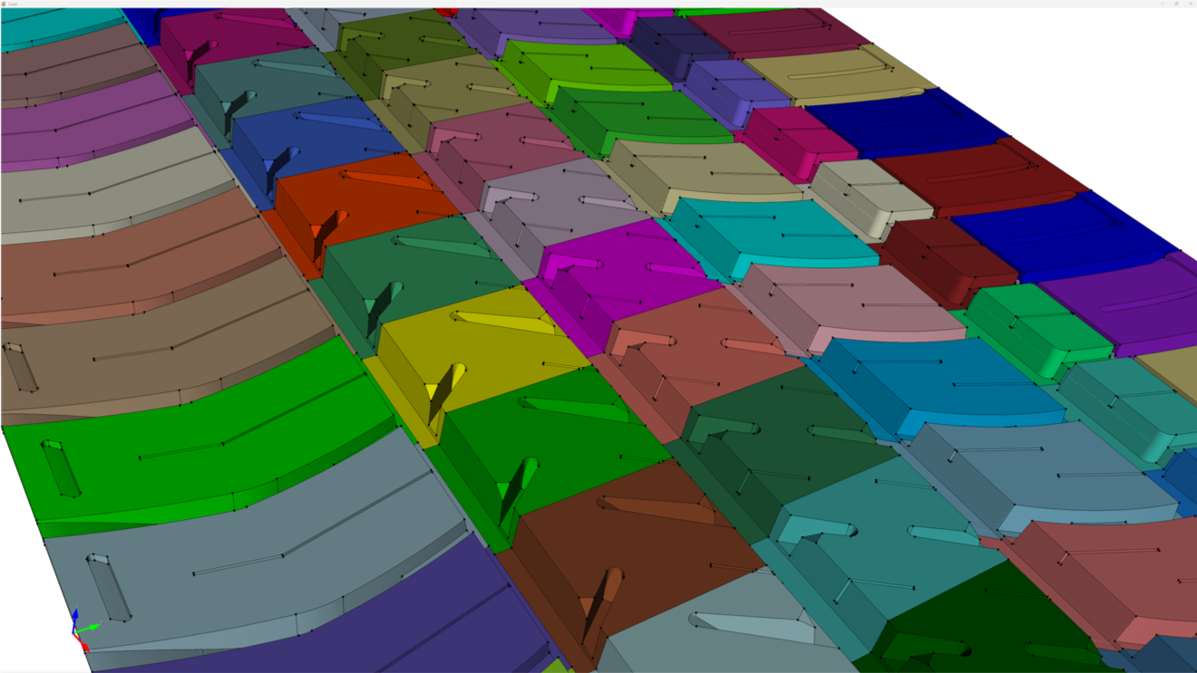
Coreform Cubit can be used to create high-quality hex meshes of tire tread designs. In this tutorial, we provide an example of a standard approach to meshing the complex geometry of a representative tire model (pictured at left).
This tutorial introduces three key Coreform Cubit techniques that are used to create quality tread meshes: subcomponent separation, automatic swept meshing, and geometry compositing.
In addition, the tutorial includes a segment illustrating how Coreform Cubit’s suite of geometry cleanup tools can be used to troubleshoot and fix model geometry issues.
Click the links below to download the tutorial slides and example files and to view the tutorial in full, or read on for a brief description of these key techniques and capabilities.
Background
Tire tread design is often characterized by CAD models of significant geometric and topological complexity. In this tutorial, we use the generally representative model shown below as our starting point.

Subcomponent separation
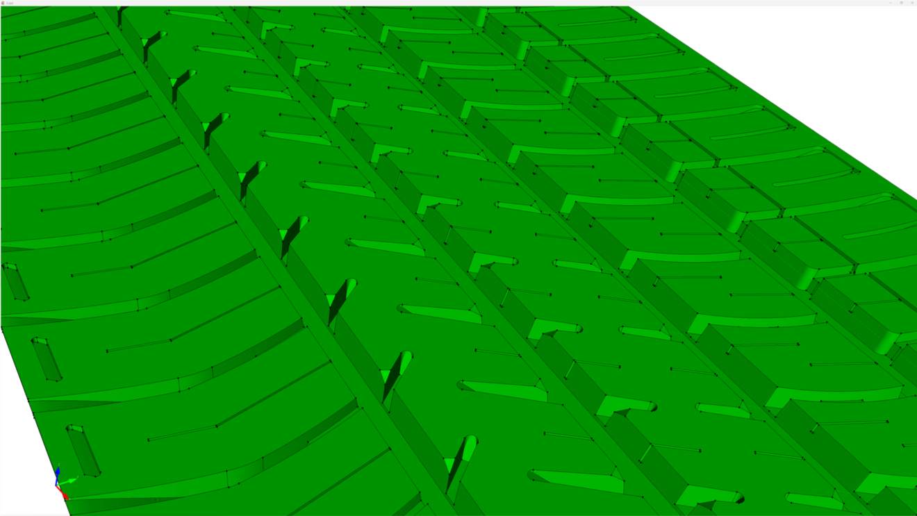
In Coreform Cubit, a standard approach to meshing challenging geometry is to separate the model into multiple subcomponents, mesh each one separately, and then recombine as a single mesh.
The image below shows the subcomponents into which the original tread model was partitioned in this tutorial rejoined into a fully-meshed tread unit.

Automatic swept meshing
The next objective is to prepare the subcomponent to be meshed using Coreform Cubit’s powerful automatic meshing schemes – the one commonly chosen for geometries like those considered here is the “many-to-one-” or multi-sweep scheme. This scheme automatically creates an extruded mesh between designated source and target surfaces when topology permits. The figure below illustrates the concept and result for one of the tread subcomponents.

Geometry compositing
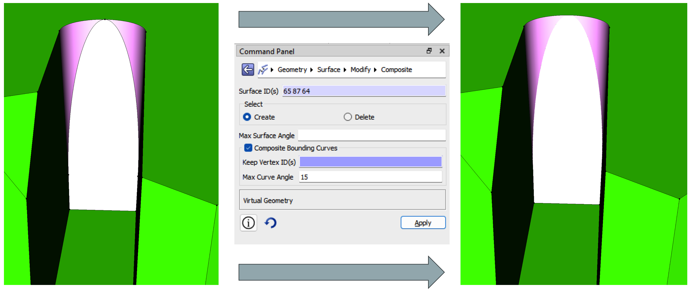
Model geometry often contains topological features that can degrade mesh quality. Coreform Cubit’s geometry compositing tools can often be used to provide a simplified virtual topology that preserves model shape while enabling the generation of higher-quality meshes. An example from the tutorial is featured below.

Geometry cleanup
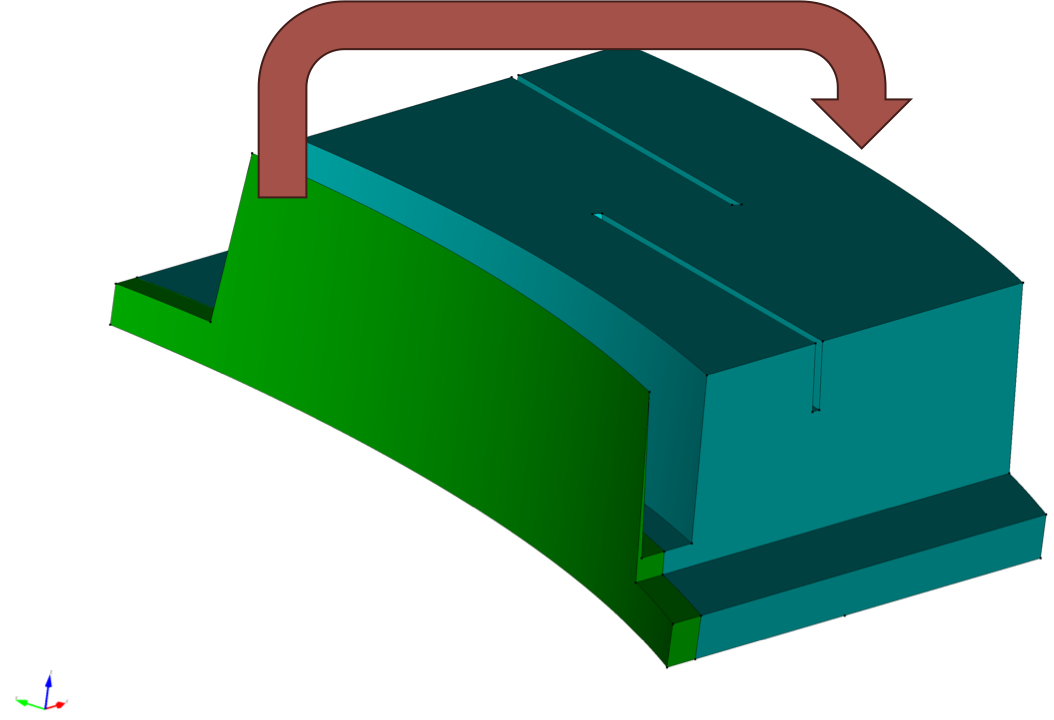
Sometimes a model contains problematic geometry of a different sort – features or constructions that might ordinarily require the model to be sent back for modifications in its CAD application of origin. Coreform Cubit, however, has an unusually powerful suite of geometry cleanup tools that can often allow such problems to be remedied in situ. In this tutorial, for example, these tools are used to slice off the green sliver volume shown in the image below and move it to the far side of the subcomponent, as indicated by the arrow.

Tutorial links and files
Watch the tutorial in the embedded video above or on Coreform’s YouTube channel here, and download the accompanying example files immediately below:
