
Coreform Cubit let us keep exact CAD geometry, eliminate overlaps, and export DAGMC and Exodus meshes in one scripted workflow—reducing uncertainty and making dose‑rate analysis reproducible.
Son Quan
Neutronics Research Group at the University of Tennessee
Background
Led by Dr. G. Ivan Maldonado, the Neutronics Research Group at the University of Tennessee advances the study of nuclear reactors across fusion and fission systems, spanning reactor physics, in‑core fuel management, radiation shielding, fuel‑cycle analysis, and materials science to improve safety, efficiency, and sustainability. Within the realm of fusion systems, the team assessed post‑operation radioactivity in a tokamak‑based fusion facility to predict dose‑rate levels and their spatial distribution—insights that support safe worker access, maintenance scheduling, and design optimization over the facility lifecycle. Finite‑element–quality meshes generated in Coreform Cubit preserve exact CAD geometry and enable robust transport and photon decay source‑sampling steps, producing reliable, reproducible dose‑rate results. For representative studies, see the group’s publications.

Fig 1: Exact CAD rendering of the FNSF fusion device, highlighting the tight clearances among components that make an exact‑geometry, overlap‑free workflow is essential. Image courtesy of Fusion Neutronics Science Facility – FNSF.
Problem
Traditional radiation transport setups often lean on constructive solid geometry, but tokamak assemblies are too complex for efficient CSG modeling. A common workaround converts CAD files into STL format; however, STL triangulation only approximates curved surfaces. In compact devices, small geometric over- or under-estimates can introduce overlaps that cause lost particles and biases. Accurate decay-photon source sampling further requires confining sources to truly activated materials; using a single global sampling volume pushes most particle samples into voids, leading to heavy reject sampling and instability. The project therefore needed a workflow that preserved the exact CAD geometry, eliminated overlaps, and produced unstructured volume meshes suitable for transport calculations and decay-photon source sampling—without inflating problem dimensions or uncertainty.

Fig 2: Triangulated STL surface exaggerates curvature and wall thickness versus exact CAD, illustrating how faceting errors can create artificial overlaps in tightly packed assemblies. (Source: https://en.wikipedia.org/wiki/STL_(file_format) )
Accurate source sampling further requires confining decay‑photon sources to actual activated materials; using a global sampling volume can trigger excessive sampling rejections or prematurely terminated runs. The project therefore needed a workflow that preserved exact CAD geometry, avoided overlaps, and produced unstructured volumetric meshes suitable for transport calculations and decay‑photon source sampling—without inflating problem size or uncertainty.
In a tokamak design, many components are very close to each other; thus, overestimating the triangulation can cause overlap between components.

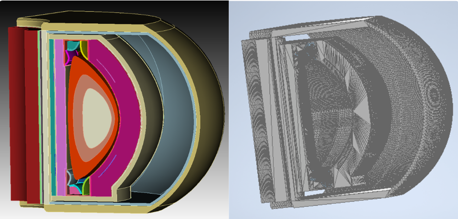
Fig 3: Exact CAD (left) versus STL representation (right) of the same device. Faceting thickens curved parts and can create interferences; maintaining exact CAD in the workflow avoids these errors.
Solution
Coreform Cubit provided a geometry‑faithful, mesh‑centric environment that connects CAD to radiation transport without loss of fidelity. The team exported exact‑geometry models directly to DAGMC for transport and generated unstructured volumetric meshes in Exodus format for decay‑photon source sampling. Cubit’s interference checks and Boolean repair resolved near‑contact overlaps. Webcut partitioned the geometry into logical regions, and local mesh sizing placed elements where transport accuracy demanded them. A Python‑driven workflow associated each meshed component with its material, decay energy, and intensity so that sources were sampled only within activated volumes and automatically excluded from voids. Together, these steps reduced lost particles from overlap regions, lowered uncertainty compared to STL‑based geometry, and yielded solver‑ready meshes purpose‑built for neutron transport and the R2S decay‑photon step of the OpenMC code.

Fig 4: Partitioning the CAD with Webcut and applying local mesh sizing in Coreform Cubit to create well‑defined regions and element densities tailored to transport and source-sampling needs.

Fig 5: Global sampling (left) pushes most samples into void, driving reject sampling and instability. Mesh‑based sampling from Exodus (right) confines sources to activated materials with correct energies and intensities, producing stable, physically faithful dose‑rate maps.
Conclusion
By preserving exact CAD geometries, eliminating overlaps, and automating exports to DAGMC and Exodus, Coreform Cubit supplied the reliable, reproducible meshing foundation the fusion neutronics research required. The result is a robust, scriptable pipeline from CAD to transport and decay‑photon source sampling, supporting confident dose‑rate predictions for complex tokamak systems.