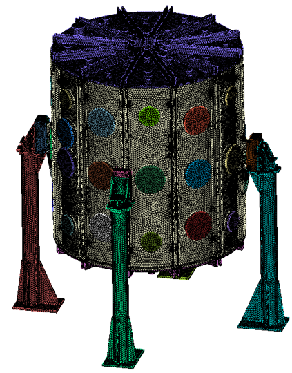
“Once properly imprinted and merged with Coreform Cubit, meshing is much smoother. While you might still need to tweak mesh sizing for individual components, it’s much easier than dealing with poorly prepared geometry.“
Bill Ellis
UKAEA
Overview
The United Kingdom Atomic Energy Authority (UKAEA) plays a pivotal role in advancing nuclear fusion research. As part of this mission, the UKAEA’s Advanced Engineering and Simulation group, led by Dr. Andrew Davis, sought to simulate physical phenomena in a full-scale Tokamak model. This ambitious task required the preparation of a 4,000-part CAD assembly for simulation using Coreform Cubit.
HPC Computational Engineer Bill Ellis spearheaded this project, leveraging Coreform Cubit to overcome challenges in meshing and geometry preparation. In this case study, we examine how Bill tackled the “monumental task” of preparing and meshing the assembly for high-fidelity simulations within a short period of using Coreform Cubit.
Problem
The team faced two significant challenges:
- Lack of a Simulation-Ready Model: Although UKAEA had a CAD model of the MAST-U (Mega Ampere Spherical Tokamak Upgrade), it lacked essential structural supports necessary for simulations. Bill explains, “The only problem at the time was that we didn’t have a simulation-ready, full-scale Tokamak model.”
- Complexity of the CAD Assembly: With thousands of individual components, the model presented difficulties in imprinting, merging, and meshing. Errors like misaligned geometry and small overlaps threatened the integrity of the mesh, complicating simulation accuracy. As Bill notes, “It’s like eating an elephant: a monumental task that you break down into small bites.”
Solution
To solve these challenges, Bill employed a methodical approach, leveraging Coreform Cubit’s advanced geometry features and scripting capability.
Step 1: Enhancing the CAD Model
Bill began by addressing the missing structural supports. Using CAD files and drawings from UKAEA’s document management system, he added the necessary components to ensure structural integrity. Collaboration with team members familiar with the Tokamak’s design was crucial.Step 2: Cleaning Up the Geometry
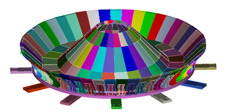
Before meshing, Bill first prepared the geometry. He used Coreform Cubit’s healing tools to address issues arising from CAD kernel inconsistencies and removed unnecessary details (e.g., bolt holes and wires) to reduce element count and streamline the mesh.
Step 3: Imprinting and Merging
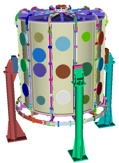
The critical step of imprinting and merging ensured that adjacent components shared like topology. Bill divided the model into smaller groups, which simplified the process and reduced the scope for troubleshooting. He also relied on tolerant imprinting to overcome small overlaps in the geometry.
“With large CAD assemblies, you’ll inevitably run into minor overlaps. Standard imprinting can struggle with geometry that has slight overlaps. Tolerant imprinting allows you to imprint within a certain tolerance.”
Step 4: Scripting with Python and C++
To handle the complexity of the model, Bill transitioned from the GUI to scripting, allowing for greater efficiency and reproducibility. Using Python and C++ scripting, he automated repetitive tasks, such as selecting and grouping geometry, and implemented version control to track progress.
Step 5: Meshing and Validation
With the geometry imprinted and merged, Bill generated a high-quality tetrahedral mesh for the entire assembly. He used Cubit’s mesh metrics to evaluate element quality and applied mesh smoothing where necessary. Validation tests, including gravity simulations and pressure differentials, confirmed the mesh’s accuracy.
