
The method that removes meshing from simulation.
Isogeometric analysis has been rigorously validated by leading researchers as the foundation for a new generation of finite element analysis, run directly on exact CAD. Coreform has spent a decade developing the technology to bring IGA into commercial engineering workflows.
What is isogeometric analysis?
The finite element method has been a remarkable success for roughly 80 years. But traditional finite element implementations cannot run on your CAD model directly. The smooth CAD geometry has to be converted into a faceted mesh first to satisfy the mathematical expectations of traditional solvers. That conversion is slow, and it throws away the exact shape you designed.
Isogeometric analysis, proposed by Dr. Thomas J.R. Hughes in 2005, set out to close the gap between CAD and analysis by using the same spline basis that CAD itself is built from. It is still a finite element method, and several thousand research papers have been published to explore its properties, which include superior accuracy per degree of freedom over the traditional Lagrange finite element basis. But using CAD splines in FEA did not, on its own, remove the hardest part of the workflow: generating analysis-suitable geometry.
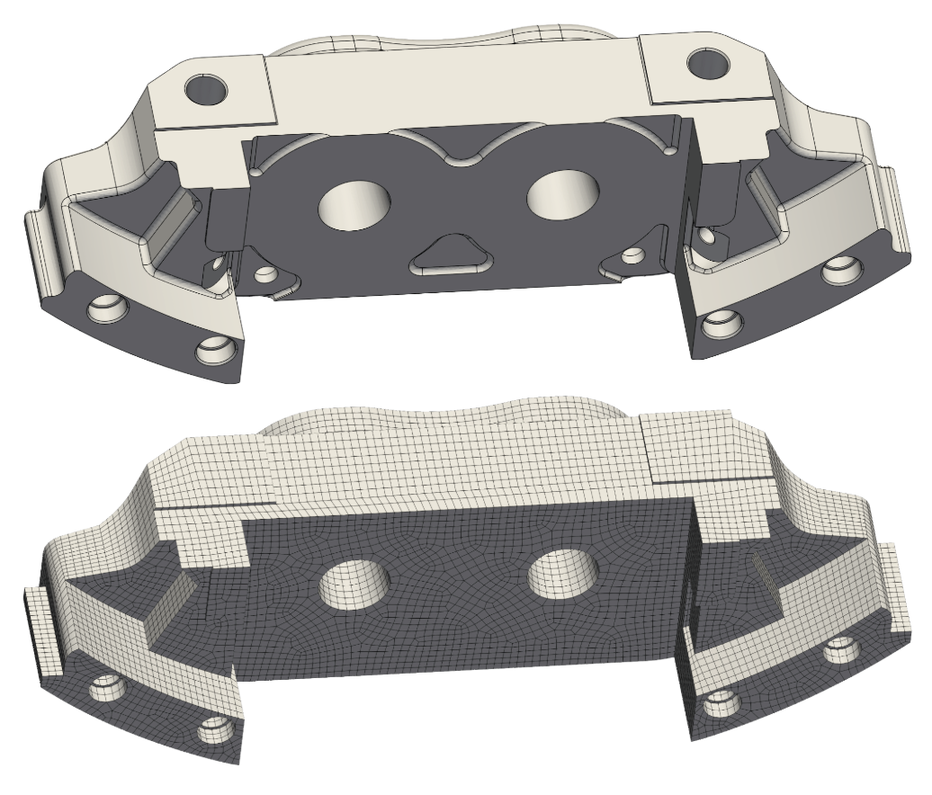
Same part. The top is CAD geometry, the bottom is a defeatured, meshed representation of the CAD, prepared for finite element analysis. This mesh took an experienced engineer 20 hours to generate using leading commercial software.
Meshing is a burden on simulation.
A 2005 study by Sandia National Laboratories found that producing quality meshes for challenging nonlinear problems ate up about 80% of the total time of a simulation project. Hundreds of Coreform interviews with engineers have confirmed that this meshing burden has only gotten worse in the two decades since as designs become more complex. Most of the effort in analysis goes into preparation, not solving.
Analysts align mesh elements to model boundaries for accuracy, and hexahedral elements are preferred. But there is no known algorithm that can automatically create a quality hex mesh from an arbirary CAD model, which is why model prep stays manual.
Analysts often resort to tet meshing, which can be done automatically but tend towards poor element quality, more expensive compute, less accuracy, less robustness, and failing unpredictably.
A 2005 Sandia National Laboratories study found that producing quality meshes for nonlinear problems consumed over 80% of total project time.
Splines: proven solver geometry.
Splines, the same math that has defined CAD for decades, are the foundation technology of isogeometric analysis.
Every modern CAD system represents geometry with non-uniform rational B-splines (NURBS): the smooth, high-order curves and surfaces that define exact shapes down to the last fillet. However, legacy finite element analysis codes were built on the Lagrange mathematical basis and there was not a straightforward way to integrate splines with these existing simulation paradigms. Notwithstanding, splines have been heavily researched and many academic papers demonstrate that they are superior basis for finite element analysis, demonstrating better accuracy per degree of freedom and robustness than Lagrange bases.
Bézier extraction, developed by Coreform's founders, opened the door for splines to be used in existing FEA software. It rewrites any spline as a set of standard Bézier elements through a local extraction operator, so an established finite element code can map spline-based analysis to the element machinery it already has.
Coreform has also developed a more general spline definition called unstructured or U-splines. This patent-pending technology defines splines over arbitrary unstructured meshes.
The Flex Representation Method.
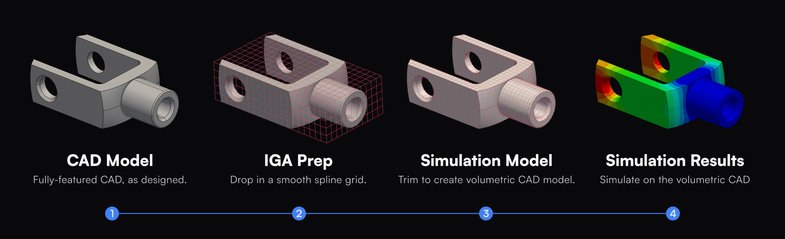
While splines introduce a superior finite element basis, on their own they do not remove the meshing step. The Flex Representation Method, or FRM, is what enables IGA to run on real CAD. It is a generalization of the finite element method.
Special quadrature handles integration on the trimmed cells, boundary conditions are enforced weakly through a penalty formulation, and the solver works directly on this immersed, trimmed representation. The painstaking, manual step of building a conforming mesh disappears, while the higher-order spline basis keeps the results accurate.
The FRM workflow
You choose how much effort to spend on the model.
Coreform's Flex Representation Method does not force a single workflow; it enables a full spectrum of approahces from a fully body-fitted spline mesh to a fully immersed model.
Fully featured, conforming
A spline mesh that conforms to the part. More manual effort to build, fastest to solve.
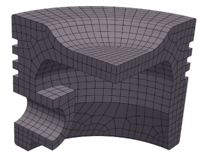
PARTIALLY BODY-FITTED
A middle ground
A balance of effort and speed.
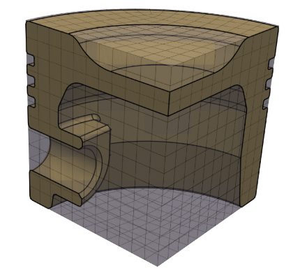
FULLY IMMERSED
Keep every feature, immerse it
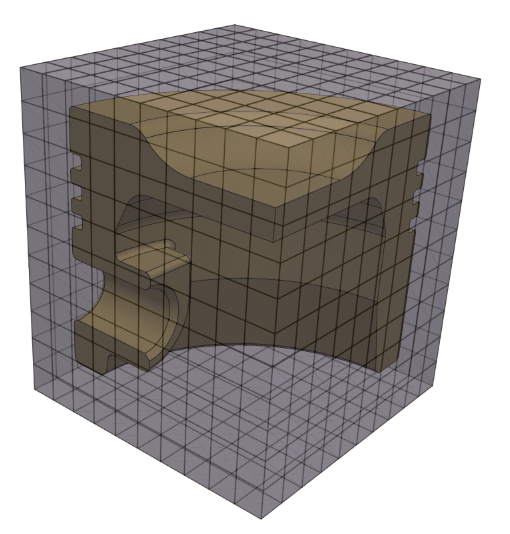
All features retained and immersed in a background mesh. Fully automatable.
Four steps, two decades.
1979
NURBS
The standard representation of freeform CAD geometry, built for design rather than analysis.
2005
IGA proposed
Dr. Tom Hughes introduces NURBS as the basis for analysis to unify CAD and FEA.
2018
U-splines
Coreform invents smooth, analysis-suitable splines over arbitrary unstructured meshes.
FRM
Immerse and trim with U-splines. The meshing step is removed and IGA runs on real CAD.
Run simulation on the geometry you designed.
Talk with our team about putting isogeometric analysis to work on your hardest problems.