Sculpt Overlay Grid Specification
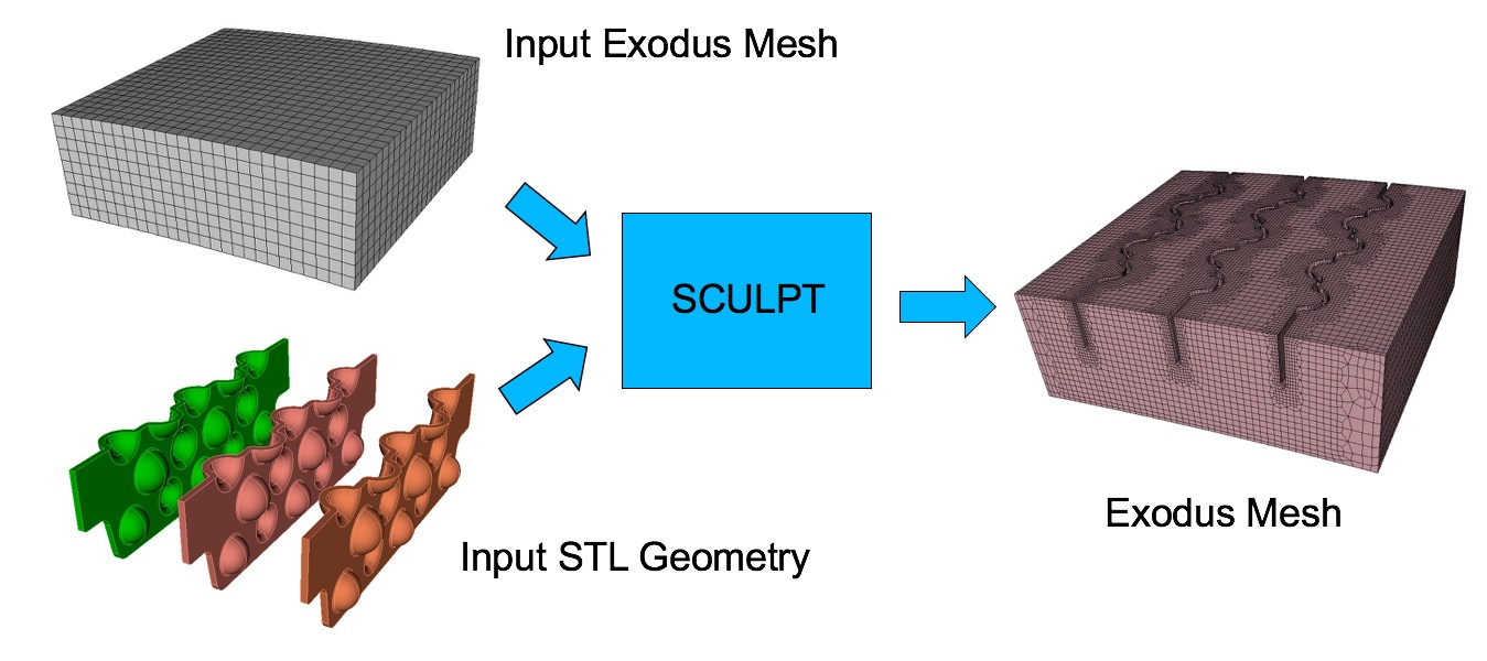
Sculpt options for setting up the overlay grid. Sculpt is an overlay-grid method that requires a base mesh that it will modify to generate the final mesh. The base mesh can be in the form of a Cartesian grid, but can also be any general unstructured hexahedral mesh defined in an exodus file (see the input_mesh option). Pamgen can also be used to generate an unstructured base mesh (see input_mesh_pamgen).
When an overlay Cartesian grid is used as the basis for the all-hex mesh that will be produced, the bounds and size of the cells defining the grid must be specified. The Cartesian grid can be defined in one of two ways:
- Define the bounding box and number of intervals in each coordinate direction. (xmin, ymin, zmin, xmax, ymax, zmax, nelx, nely, nelz)
- Define a cell_size. Sculpt will then automatically define the Cartesian grid coordinates and intervals by evaluating the bounding box of the input geometry and adding a small number of cells in each coordinate direction.
Other options for setting up the Cartesian base grid include align and expand which are normally used with the second method. The align option will automatically rotate the grid to best match the characteristic direction of the geometry rather than maintaining alignment with the global Cartesian directions. The expand option over-rides the default expansion of the Cartesian grid beyond the bounding box of the geometry and allow the user to specify a specific expansion percentage.
Overlay Grid Specification   -ovr     --overlay
  --nelx                     -x    <arg> Num cells in X in overlay Cartesian grid
  --nely                     -y    <arg> Num cells in Y in overlay Cartesian grid
  --nelz                     -z    <arg> Num cells in Z in overlay Cartesian grid
  --xmin                     -t    <arg> Min X coord of overlay Cartesian grid
  --ymin                     -u    <arg> Min Y coord of overlay Cartesian grid
  --zmin                     -v    <arg> Min Z coord of overlay Cartesian grid
  --xmax                     -q    <arg> Max X coord of overlay Cartesian grid
  --ymax                     -r    <arg> Max Y coord of overlay Cartesian grid
  --zmax                     -s    <arg> Max Z coord of overlay Cartesian grid
  --cell_size                -cs   <arg> Cell size (nelx, nely, nelz ignored)
  --align                    -a          Automatically align geometry to grid
  --bbox_expand              -be   <arg> Expand tight bbox by percent
  --input_mesh               -im   <arg> Input Base Exodus mesh
  --input_mesh_blocks        -imb  <arg> Block ids of Input Base Exodus mesh
  --input_mesh_material      -imm  <arg> Material definition with input mesh
  --input_mesh_pamgen        -imp  <arg> Input Base mesh defined by Pamgen
  --join_parallel            -jp   <arg> Join parallel files

Sculpt Command Summary
Number of Intervals X
Command: nelx     Num cells in X in overlay Cartesian grid

Input file command:   nelx <arg>
Command line options: -x <arg>
Argument Type:        integer > 0
Command Description:
Defines the number of intervals in the x direction of the base Cartesian grid used for defining the volume fraction definition and meshing For best results the intervals specified should result in approximately equilateral cells.
See also nely, nelz
Number of Intervals Y
Command: nely     Num cells in Y in overlay Cartesian grid

Input file command:   nely <arg>
Command line options: -y <arg>
Argument Type:        integer > 0
Command Description:
Defines the number of intervals in the y direction of the base Cartesian grid used for defining the volume fraction definition and meshing For best results the intervals specified should result in approximately equilateral cells.
See also nelx, nelz
Number of Intervals Z
Command: nelz     Num cells in Z in overlay Cartesian grid

Input file command:   nelz <arg>
Command line options: -z <arg>
Argument Type:        integer > 0
Command Description:
Defines the number of intervals in the z direction of the base Cartesian grid used for defining the volume fraction definition and meshing For best results the intervals specified should result in approximately equilateral cells.
See also nelx, nely
Xmin Bounding Box Range
Command: xmin     Min X coord of overlay Cartesian grid

Input file command:   xmin <arg>
Command line options: -t <arg>
Argument Type:        floating point value
Command Description:
Defines the minimum x coordinate of the bounding box or range of the Cartesian mesh to be used for meshing.
See also ymin, zmin, xmax, ymax, zmax.
Ymin Bounding Box Range
Command: ymin     Min Y coord of overlay Cartesian grid

Input file command:   ymin <arg>
Command line options: -u <arg>
Argument Type:        floating point value
Command Description:
Defines the minimum y coordinate of the bounding box or range of the Cartesian mesh to be used for meshing.
See also xmin, zmin, xmax, ymax, zmax.
Zmin Bounding Box Range
Command: zmin     Min Z coord of overlay Cartesian grid

Input file command:   zmin <arg>
Command line options: -v <arg>
Argument Type:        floating point value
Command Description:
Defines the minimum z coordinate of the bounding box or range of the Cartesian mesh to be used for meshing.
See also xmin, ymin, xmax, ymax, zmax.
Xmax Bounding Box Range
Command: xmax     Max X coord of overlay Cartesian grid

Input file command:   xmax <arg>
Command line options: -q <arg>
Argument Type:        floating point value
Command Description:
Defines the maximum x coordinate of the bounding box or range of the Cartesian mesh to be used for meshing.
See also xmin, ymin, zmin, ymax, zmax.
Ymax Bounding Box Range
Command: ymax     Max Y coord of overlay Cartesian grid

Input file command:   ymax <arg>
Command line options: -r <arg>
Argument Type:        floating point value
Command Description:
Defines the maximum y coordinate of the bounding box or range of the Cartesian mesh to be used for meshing.
See also xmin, ymin, zmin, xmax, zmax.
Zmax Bounding Box Range
Command: zmax     Max Z coord of overlay Cartesian grid

Input file command:   zmax <arg>
Command line options: -s <arg>
Argument Type:        floating point value
Command Description:
Defines the maximum z coordinate of the bounding box or range of the Cartesian mesh to be used for meshing.
See also xmin, ymin, zmin, xmax, ymax.
Cell Size
Command: cell_size     Cell size (nelx, nely, nelz ignored)

Input file command:   cell_size <arg>
Command line options: -cs <arg>
Argument Type:        floating point value
Command Description:
Defines a target edge size for the cells of the base Cartesian grid. Both interval and cell_size can not be specified simultaneously. If cell_size is used without a range specification, a bounding box of the geometry will be computed and used as the default range
Align
Command: align     Automatically align geometry to grid

Input file command:   align
Command line options: -a
Command Description:
The align option will attempt to orient the Cartesian grid with the main dimensions of the geometry. This is done by defining a tight bounding box around the geometry using an optimization procedure where the objective is to minimize the difference in volume between an enclosing box and the geometry. Using the align command will override any bounding box parameters previously entered and will build an "aligned" bounding box around the full geometry. It is currently only implemented for STL geometry and will ignore any other diatom definitions. Note that this option will also write temporary stl and diatom files to the working directory.
Bounding Box Expansion Factor
Command: bbox_expand     Expand tight bbox by percent

Input file command:   bbox_expand <arg>
Command line options: -be <arg>
Argument Type:        floating point value
Command Description:
Sculpt will measure a tight bounding box of the input model and expand the box by the specified percentage in x, y and z. Input value can be any positive or negative floating point value where 1.0 represents 100 percent expansion. If not specified, the default will add about 2.5 cell widths to the bounding box on each side. This option should be used with the cell_size option. It will be ignored if a specific bounding box has been defined (ie. xmin, ymin, etc...).
Input Base Exodus Mesh
Command: input_mesh     Input Base Exodus mesh

Input file command:   input_mesh <arg>
Command line options: -im <arg>
Argument Type:        file name with path
Command Description:
Option to import an Exodus file to use as the base mesh for Sculpt. Sculpt's meshing procedure requires a base mesh from which geometry is recovered and captured. The default base mesh is a Cartesian grid that is defined by specifying a bounding box and intervals. The input_mesh option permits a general hexahedral mesh to be used as the base mesh instead of a Cartesian grid. This option currently supports a serial and parallel Exodus files containing HEX8 elements with any number of blocks.
The input_mesh option can also be used in parallel. Sculpt currently requires the mesh to be decomposed prior to running sculpt. The SEACAS decomp tool can be used to pre-process any exodus mesh to break it into multiple meshes ready for use in sculpt. SEACAS is an open source library available on github. For example, when using four processors with sculpt, you would use the following command:
decomp -p 4 simple-mesh.g
The result would be the four meshes:
    simple-mesh.g.4.0
    simple-mesh.g.4.1
    simple-mesh.g.4.2
    simple-mesh.g.4.3
Once the base mesh has been decomposed, Sculpt can be run. In this case, the input_mesh option would use the root simple-mesh.g as the argument.
input_mesh = simple-mesh.g
If the -j 4 option is used, sculpt will look for 4 meshes in the current working directory with the appropriate root and extension.
Four different options are supported for describing the geometry when using the input_mesh option:
- stl_file: A single file containing a water-tight faceted description of the geometry. Note that only the portion of the STL file completely contained within the base mesh will be represented in the final mesh.
- diatom_file: May contain analytic descriptions of geometric primitives and/or references to multiple STL files.
- input_spn: The materials of the cells in the spn file are mapped onto the elements of the input mesh using inverse distance-weighted interpolation. As with the stl and diatom files, only the portion of the spn file completely contained within the base mesh will be represented in the final mesh. The input_mesh_blocks option can be used in conjunction with the spn_file option to limit the scope of the mapping of material from the spn file to the mesh file. If this options is used, only elements in the specified blocks will get mapped to. For more details, see the input_mesh_blocks option.
- Element Variables: The geometry may also be described by element variables in the Exodus file. Element variables should represent material volume fractions where the sum of element variables for any one cell should be between 0.0 and 1.0. Any number of element variables may be used where each unique variable defined will describe an element block in the final Exodus mesh produced. if the sum of element variables is less than 1.0 for any one element, a void material will be assumed and removed from the base mesh unless the mesh_void option is used.
Limitations:
- An STL file and element variables cannot be used in the same input. If element variables are present in the Exodus file and an STL or Diatom file is used, the element variables will be ignored.
- If an input mesh is used, any Cartesian grid specifications will be ignored (ie. nelx, xmin, xmax).
- The adapt_type option will work only for an exodus input mesh that defines a mapped mesh. Adapt types vfrac_average (4) and vfrac_difference (6) are currently the only criteria supported with the input_mesh option.
Blocks of Input Base Exodus Mesh
Command: input_mesh_blocks     Block ids of Input Base Exodus mesh

Input file command:   input_mesh_blocks <arg>
Command line options: -imb <arg>
Argument Type:        integers > 0
Command Description:
This option is valid when specifying both input_mesh and spn_file. Using this option, the materials of the cells in the spn file are mapped onto only the elements of the specified blocks in the input_mesh file. The remaining blocks are treated as void. The behavior without this option maps the materials of the cells in the spn file onto elements of all blocks in the input_mesh file.
Material Definition with Input Mesh
Command: input_mesh_material     Material definition with input mesh

Input file command:   input_mesh_material <arg>
Command line options: -imm <arg>
Argument Type:        integers > 0
Input arguments: geometry (0)
                 blocks (1)
                 proximity_blocks (2)
                 geometry_and_blocks (3)
Command Description:
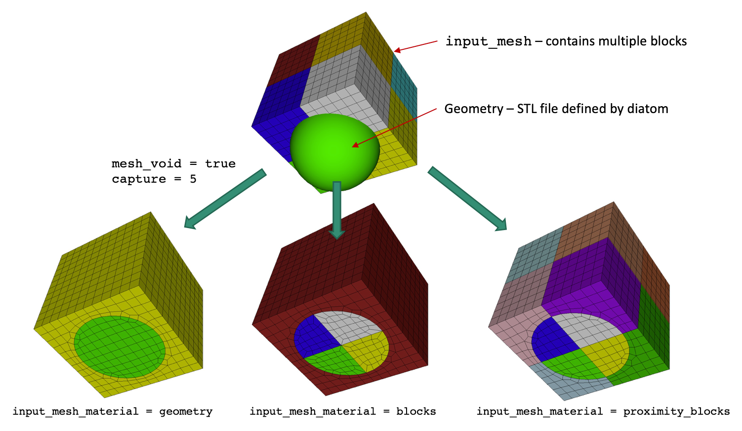
This option is valid when specifying an 'input_mesh' . Using this option, the material definition in the final mesh may be defined based on the material definitions on the geometry, or based on the block ids of the input mesh. For example, a diatom file defining geometry would have materials defined which are used to define the materials in the final mesh. The default is to use material definitions on the geometry. Possible options are:
- geometry (0): Material defined by geometry. Block definitions in input file will be ignored. Instead, only the geometry defined from the STL or diatom geometry definition will be respected.
- blocks (1): Material defined by blocks in input mesh. Both the geometry definition defined by the STL/diatom file and by the block definition in the input file will be used to construct the mesh. Block definitions used in the final mesh will be defined only by the input_mesh blocks, ignoring any material definitions in the diatom file. Note that pillowing may be required to maintain mesh quality where interior intersecting interfaces between STL/diatom geometry and block geometry occur. When used with the mesh_void option, element block groupings are made only for the interior of the STL/diatom geometry. Elements in the void region are assigned to the designated void_mat
- proximity_blocks (2): Material defined by blocks in input mesh based on
proximity method. Geometric interfaces in the final mesh will be defined based
on the STL/diatom definition, similar to the geometry (0) method.
Material/block assignment for elements is defined only by the proximity of
individual elements contained within the regions defined by blocks in the
input mesh. Block assignment is made by collecting all elements in the final
mesh whose centroid falls within a given block in the input mesh. Note that
this method avoids the interior intersections and subsequent poor mesh quality
that may result from the blocks (1) method described above. As a
result, interior interfaces may be non-continuous (stair-step). In order to
avoid collisions between the material ID defined in the diatom file and those
defined in the input_mesh, block IDs in the final mesh are assigned based on
the following definition:
ID = (diatom_material_ID-1)*max_input_mesh_block_ID + input_mesh_block_IDIf the max_input_mesh_block_ID is less than the max_diatom_material_ID, then the following definition is used:ID = (input_mesh_block_ID-1)*max_diatom_material_ID + diatom_material_ID - geometry_and_blocks (3): Material defined by the stl geometry and the blocks in input mesh. Both the geometry definition defined by the STL/diatom file and by the block definition in the input file will be used to construct the mesh. Block definitions used in the final mesh will be defined by both the material IDs defined in the diatom file and the input_mesh blocks. Where stl geometry overlaps a material block defined in the input_mesh, the stl geometry material will take precedence.
Input Base mesh defined by Pamgen
Command: input_mesh_pamgen     Input Base mesh defined by Pamgen

Input file command:   input_mesh_pamgen <arg>
Command line options: -imp <arg>
Argument Type:        file name with path
Command Description:
Option to use Pamgen to create a base mesh for Sculpt. Pamgen is an open source meshing tool developed at Sandia for generating hexahedral meshes from geometric primitives. In addition to being a stand-alone meshing solution, it is a parallel tool that is integrated as an inline meshing tool for Sandia's shock physics simulation tool, Alegra. Pamgen has also been integrated in Sculpt as a solution for automatically defining a base mesh.
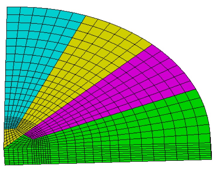
The input_mesh_pamgen option permits a mesh defined my Pamgen input parameters to define the base mesh. A limited set of brick and cylinder primitives are supported by Pamgen. The name of an ascii file containing the pamgen mesh definition is used as the argument for this option. The following is a simple example of a pamgen mesh description. It generates a partial cylinder with a span of 90 degrees and height of 1.0. Other parameters allow for specific interval and sizing specifications as well as block/material identification.
    mesh
        radial trisection
            trisection blocks, 2
            zmin -0.00075
            numz 1
                zblock 1 1. interval 8
            numr 3
                rblock 1 2.0 interval 8
                rblock 2 3.0 interval 8
                rblock 3 4.0 interval 8
            numa 1
                ablock 1 90. interval 24
        end
        set assign
            nodeset, ilo, 100
            block sideset, ihi, 45, 2
        end
    end
For a full description of Pamgen and input parameters see the following document:
David M. Hensinger, Richard R. Drake, James G. Foucar, Thomas A. Gardiner, "Pamgen, a Library for Parallel Generation of Simple Finite Element Meshes", Sandia Report SAND2008-1933 (2008)
Similar to the input_mesh option, the same geometry input options are available. They include stl_file, diatom_file and input_spn. See the input_mesh option for additional details and limitations.
Join Parallel Files
Command: join_parallel     Join parallel files

Input file command:   join_parallel <arg>
Command line options: -jp <arg>
Argument Type:        true/false
Input arguments: off (0)
                 false (0)
                 on (1)
                 true (1)
Command Description:
Import a set of files, one per processor, using the base name defined by the import_mesh option. When not used (default), the assumption of input exodus meshes is to include parallel (nemesis) data where parallel relationships between neighboring processors has already been established. This is normally done by using the SEACAS decomp tool to decompose a single exodus mesh into multiple files.
If the join_parallel option is used, sculpt assumes the parallel relationships are not included and will establish these relationships based on proximity of node locations at processor boundaries. Note that the file naming convention should follow the standard exodus parallel file naming convention. For example, a mesh spread across 4 files would be named:
    brick.e.4.0
    brick.e.4.1
    brick.e.4.2
    brick.e.4.3
This option is currently only implemented for axis aligned rectangular processor domains. This option can also be used to just stitch exodus files and dump resulting files without any additional sculpt operations. The following is an example of a sculpt input file that does simple stitching without any additional sculpt operations:
    begin sculpt
      input_mesh = brick.e
      exodus_file = brick_ouput
      join_parallel  = true
      input_mesh_material = blocks
      stair = fast
    end sculpt