![]()
Coreform Cubit 2025.8 User Documentation
![]()
The find mesh intersection capability finds intersecting mesh between blocks, bodies, volumes, or surfaces. This command is useful for identifying cases where the geometry does not intersect but the mesh does. The command can find intersecting 2-dimensional mesh by specifying a list of surfaces, or 3-dimensional mesh by specifying blocks, bodies, or volumes. Surfaces that have mesh between them that intersects within a tolerance of 1e-6 are located. Finding surfaces with intersecting mesh is done using the command:
Find Mesh Intersection {Block|Body|Surface|Volume} <id_list> [with {Block|Body|Surface|Volume} <id_list>] [low <value=0.0001>] [high <value>] [exhaustive] [worst <num_worst>] [draw] [log] [group<'name'>]
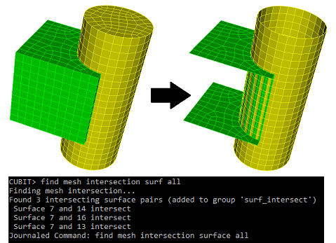
To find intersections between 2-dimensional mesh surfaces must be specified. If intersections are found, the surfaces containing the intersecting mesh are drawn (Figure 1) and the put into a group named 'surf_intersect', unless the user has specified another name using the group <'name'> option. Also, the ids of the intersecting surface pairs are printed to the terminal,

Figure 1. "Find mesh intersection surface all"
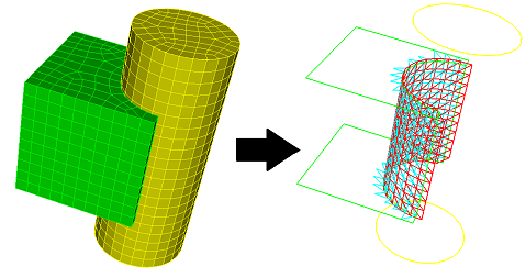
The draw option will draw the surfaces and intersecting mesh in wire frame mode, allowing the user to see exactly where on the surface the mesh intersection is (Figure 2).

Figure 2. "Find mesh intersection surface all draw"
Detecting mesh intersections between surfaces works entirely off of the mesh, converting the mesh into triangular facets. (The facetted representation is what you see in a shaded view in the graphics). For example, a quad is split into two triangles. Higher order 2D elements are split into multiple triangles.
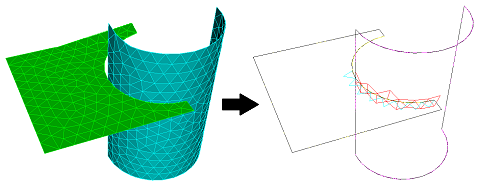
The command below will draw the mesh intersection for only a pair of surfaces. The surfaces and intersecting mesh are drawn in wire frame mode, allowing the user to see exactly where on the surface the mesh intersection is.
Draw Surface <id> <id> mesh intersection [add] [include_volume]

Figure 3. Draw Mesh Intersection
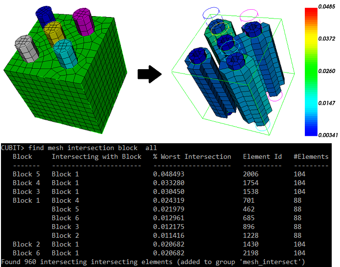
With 3-dimensional entities mesh element intersections can be located by specifying entities: blocks, bodies, or volumes. If intersections are found the intersecting elements are put into a group named 'mesh_intersect' unless the user has specified another name using the group <'name'> option. Data is printed to the terminal detailing the intersections. The largest intersection value is reported for each pair of intersecting entities (blocks, volumes, or bodies). This value is the fraction of an element's volume (which element belongs to the entity in the first column) that intersects elements belonging to the entity in the second column. See Figure 5 below. The information printed in columns from left to right is:

Figure 5. "Find mesh intersection block all draw"
If the with option is used, the user specifies additional entities. The additional entities will not be reported in the first column of the output. This allows the user to focus on entities of interest without outputting too much data to the terminal. See Figure 6 below.

Figure 6. "Find mesh intersection block 1 with block all"
The low and high options set how much cumulative intersection should be detected. A low value of 0.1 would ignore elements that do not intersect more than 10% of their volume. Similarly, a high value of 0.5 would discard elements that intersect more than 50% of their volume. Both low and high can be used simultaneously. The default for the low value is 0.0001
The exhaustive option examines all elements for intersection. The default is to only examine elements with nodes on the boundary of the specified entities, anticipating that the intersections will occur mostly at boundaries.
The worst parameter limits the printout to the 'n' worst entities with elements of the highest intersections. The intersection fraction reported here is the cumulative intersection an element has with elements of all other entities in the check.
The draw option draws the intersecting elements using a color spectrum, red corresponding to high intersection and green to low. The color is according to cumulative intersection, as described in the worst option.
If the log option is specified, the output from the command will also be sent to a file named "mesh_intersection01.txt", with the number used in the file name incremented as needed. This becomes useful when you have hundreds of volumes with intersections.
Note: