Free Meshes
A free mesh is a mesh that is not associated with any underlying geometric entities. A free mesh contains only mesh elements (hexahedra, triangles, edges, nodes, etc), and not volumes, surfaces, etc. Since there is no underlying geometry, operations on free meshes are limited. The following operations can be performed on free meshes in some capacity:
- Creating a free mesh
- Creating mesh-based geometry to fit a free mesh
- Mesh merging
- Mesh transformations
- Mesh smoothing
- Mesh quality operations
- Mesh refinement
- Cleaning up a free mesh
- Assigning boundary conditions
- Skinning a free mesh
- Mesh deletion
- Bottom-up element creation
- Exporting a free mesh
Creating a free mesh
A free mesh can be created in three ways.
- Importing a mesh into Cubit using the Import Mesh [No_Geom] command. This option is discussed in detail in Importing Exodus II Files.
- Disassociating an existing mesh from its geometry
- Creating a mesh with the geometry-tolerant mesh scheme
Disassociating a mesh from its geometry
The command to disassociate a mesh from existing geometry is:
Disassociate Mesh [From] {Volume|Surface|Curve|Vertex} <id_range>
For example:
brick x 10
mesh volume all
disassociate mesh from volume 1
delete volume 1
When a mesh is disassociated from its geometry, a group called 'disassociate elements' is created to contain the free mesh.
Creating Mesh-Based Geometry to fit a Free Mesh
It is possible to create underlying mesh-based geometry to own a free mesh. It is similar in functionality to the Import Mesh Geometry command, but it does not require the extra import/export step. For example, a user would be able to read in a free mesh, fix any mesh problems, and then create the mesh-based geometry without having to write the mesh to a file first. The command syntax is:
Create Mesh Geometry {Hex|Tet|Face|Tri|Block} <range> [no_nodeset] [no_sideset] [exclude block <range>] [Feature_Angle <angle=135>] [Acis] [Keep]
The command also applies to any subset of the mesh. For example, you can create mesh geometry for a group of hexes or element blocks.
If the keep option is specified, the mesh will be duplicated so you will have two copies of the mesh: The original mesh and the new mesh that is owned by the new MBG geometry. If the keep option is not specified, the existing mesh will be reused, and duplicate elements will not be created. Elements will now be owned by the new MBG geometry. The command will check for mesh ownership and will issue a warning. Use the keep option if the mesh is already owned. The keep option is not specified by default.
By default, genesis entities will be used as criteria for building the new MBG geometry. The no_nodeset and no_sideset options can be specified to prevent this. Any genesis entities defined on the free mesh are transferred to the new MBG geometry. When the keep option is used copies of genesis entities are made on the new MBG geometry.
The exclude block option excludes specified blocks from feature angle detection. Any volumes created from these excluded blocks will have only one surface.
The Acis option will attempt to create ACIS geometry from the mesh. This option is an alpha feature and can only be used if developer commands have been turned on. For more detail see: Acis Geometry From Mesh
Merging a free mesh
To merge two free meshes, the equivalence command may be used. The command syntax is:
Equivalence Node <range> [Tolerance <value>] [Preview]
All nodes in the given range that are within the specified tolerance will be merged. The merged and unchanged (unmerged) nodes are put into groups. The maximum distance between merged nodes, and the minimum distance between unmerged nodes, are listed for the user because if these values are close together it can indicate a problem with the Tolerance. Nodes within tolerance and part of the same element will not be merged. This prevents collapsing elements into degenerate forms. With the Preview option, the nodes aren't actually merged, but the ones that would have merged are drawn and grouped. For example:
br x 10
volume 1 copy move x 10
mesh volume all
disassociate mesh from volume 1 2
delete volume 1 2
equivalence node all tolerance 0.05
## merges all nodes that are within 0.05 of each other
Free Mesh Transformation Operations
Mesh transformations for free meshes are achieved through the use of the group transformation commands, given in Basic Group Operations. All members of a free mesh are automatically assigned to a group. These groups can then be modified using group operations. The following command sequence illustrates how transformations might be applied to a free mesh.
brick x 10
mesh volume 1
disassociate mesh from volume 1
delete volume 1
group disassociated_elements move x 10
group disassociated_elements rotate 15 about x
group disassociated_elements scale 0.25
group disassociated_elements reflect 1 1 0
group 'node_group' add node 1 to 121
group node_group move z 5
##The moved nodes do not also move the attached geometry, as one might
expect.
If a group is composed of mesh entities, these commands will only operate on the nodes in the group. All nodes of the group will be moved, scaled, rotated, or reflected as specified. If there are no nodes in the group, Cubit will return an error. Including all nodes in the group will transform the whole model. Including only a subset of nodes will transform those nodes and their enclosed elements, but it will not transform the whole mesh.
Disassociated mesh elements cannot be copied using the Group copy commands. To create a copy they must be exported and reimported. Alternatively, they can be associated with mesh-based geometry, and then copied using the typical copy commands.
Extruding Mesh Elements
Mesh elements can be extruded to create new elements from existing nodes, edges, faces or triangles. There are two forms of the extrude command as follows:
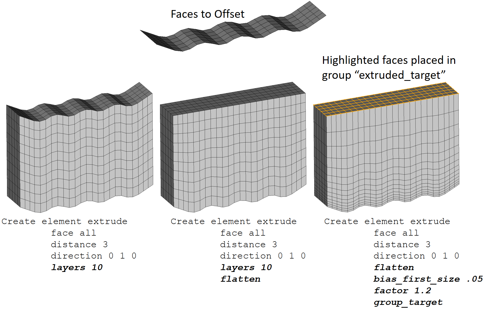
Create Element Extrude {Node|Edge|Face|Tri} <element_list> Direction <options> [Distance <value>] {Layers <num_layers | {bias_first_size <value> factor <value>}} [Twist <angle> Axis <axis_options>] [flatten] [group_target]
Create Element Extrude {Node|Edge|Face|Tri} <element_list> Along Curve <curve_list> [Layers <num_layers]
In the first form of the command, a direction and distance are specified to define the extrusion. To define node spacing along the extrusion, the command takes either the layers or bias_first_size and factor parameters, but not both. Specifying a value for the layers option determines how many evenly sized elements will be created in the given distance. The bias_first_size and factor parameters define a bias that will be used along the extrusion distance. When specifying entities to be extruded which are either non-planar, or not orthogonal to the extrusion direction, the flatten parameter results in the extrusion terminating on a single plane orthogonal to the extrusion direction. The optional group_target parameter places all of the faces, tris, edges, or nodes at the end of the extrusion into a group named "extruded_target" which can be conveniently used to define a subsequent extrusion with a different set of extrusion parameters. Twist can also be specified and requires an angle of twist and a twist axis.
The figure below illustrates the new flatten, bias_first_size, factor, and group_target keywords. At the top is a set of non-planar faces to offset. On the bottom-left, each node on all of the faces are extruded the same amout resulting in a target of the extrusion with identical curvatuve to the input faces. In the bottom-middle, the flatten keyword is used, resulting in the extrusion terminating on a single plane. In the bottom-right, the bias_first_size, factor, and group_target keywords are used, resulting in a biased extrusion, and the creation of a group named "extruded_target", which contains the faces on the end of the extrusion.
In the second form, a curve is specified, along with the input entities will be extruded. Extruding along a curve supports the layers parameter, but does not currently support the distance, bias_first_size, factor, flatten, twist or group_target parameters.
#Extrude a face in a given direction:
create node location 0 0 0
create node location 1 0 0
create node location 1 1 0
create node location 0 1 0
create face node 1 to 4
create element extrude face 1 direction 0 0 1 distance 3 layers 3
create element extrude face 1 direction 0 0 1 distance 3 layers 3 twist
90 axis direction 0 0 1 origin 0 0 0
#Sweep face along curve
create node location 0 0 0
create node location 1 0 0
create node location 1 1 0
create node location 0 1 0
create face node 1 to 4
create vertex location position 0 0 0
create vertex location position 0 .2 1
create vertex location position 0 1 2
create vertex location position 0 3 2
create vertex location position 0 4 1
create vertex location position 0 5 0
create curve spline vertex 1 2 3 4 5
create element extrude face 1 layers 5 along curve 1
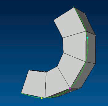
Figure 1. Extruding mesh elements along a spline
Offsetting Mesh Elements
Faces and triangle elements can be used to create hexahedral and wedge elements from an offset command. The default offest direction is normal to the selected face. The Oppposite_normal option will use the reverse direction. The layers parameter determines how many elements will be created in the given direction.
Create Element Offset {Face|Tri} <element_list> [Normal_to|Opposite_normal] {Distance <value>] [Layers <num_layers>]
#Create wedge and hex elements from face and tri
elements via offset
create node location 0 0 0
create node location 1 0 0
create node location 1 1 0
create node location 0 1 0
create node location 2 0 1
create node location 2 1 1
create node location 1 2 0
create face node 1 to 4
create face node 3 2 5 6
create tri node 7 4 3
create tri node 7 3 6
create element offset face all tri all distance 3 layers 3 opposite_normal
Revolving Mesh Elements
Elements can be created by revolving an existing element around a given axis. The Attempt_fix parameter will try to fix any poorly formed hex elements by collapsing them into wedge elements. Angle determines the amount of rotation around the axis. The Layers option determines how many elements will be created in the given rotation. The quadratic option will result in the creation of quadratic elements. For example, it can result in HEX20 or TET10 elements being created. To further specify the element type, for the created elements, one may put them into a block.
Create Element Revolve {Edge|Face|Tri} <element_list> Axis <axis_options> Angle <angle> [Layers <num_layers>] [Attempt_fix] [quadratic]
#Revolve 2 faces around the Y-axis and collapse
inner hexes to wedges
create node location 0 0 0
create node location 1 0 0
create node location 1 1 0
create node location 0 1 0
create node location 2 0 0
create node location 2 1 0
create face node 1 2 3 4
create face node 2 5 6 3
create element revolve face 1 2 axis direction 0 1 0 angle 180 layers 4 attempt_fix
block 1 hex all
block 2 wedge all
block 1 element type hex8
block 2 element type wedge6
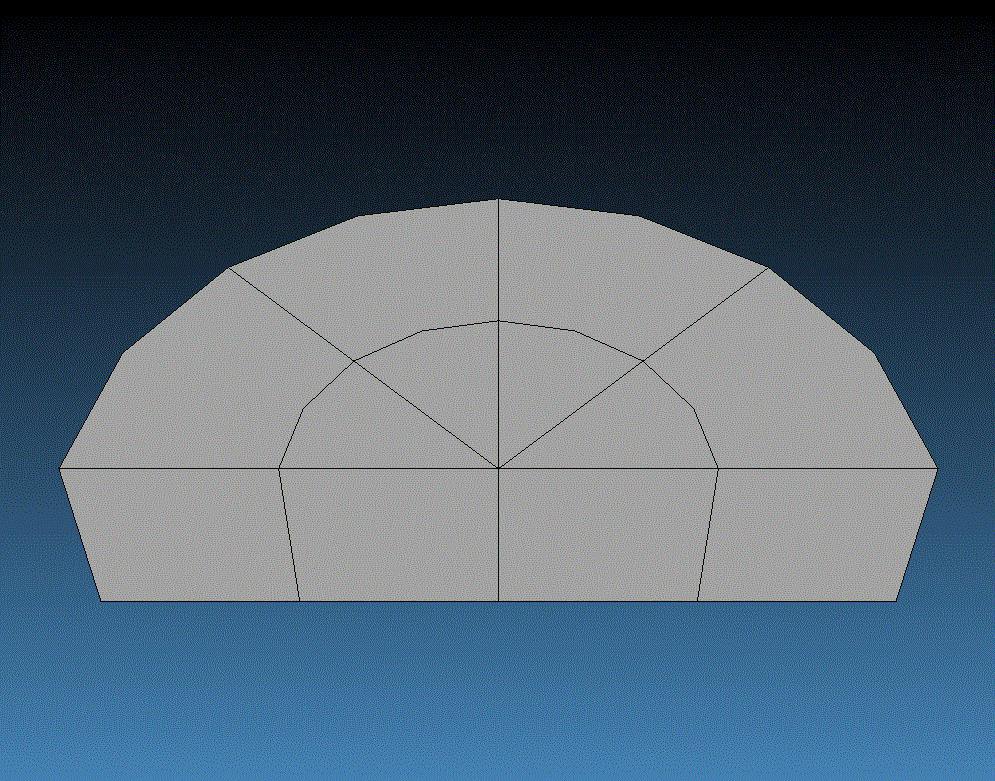
Figure 2. Revolving free mesh elements to create hex and wedge elements
Smoothing a free mesh
Interior nodes can be smoothed using commands such as smooth hex all, or smooth tet all in block 100. These commands will smooth only the interior node on the elements used in the command. The nodes on the boundary will remain unchanged. To smooth nodes on a boundary, the target smoothing option can be used. Targeted smoothing allows the user to smooth a group of mesh elements to a surface or curve that is not their owner. Targeted smoothing is discussed under Mesh Smoothing. The following sequence of commands illustrate the capability of smoothing a free mesh to a target surface.
sphere rad 25
webcut vol 1 plane xplane offset 18
delete vol 2
webcut volume 1 plane yplane offset 8
webcut volume 1 plane yplane offset -8
delete vol 1 3
surf 16 copy
delete vol 4
surf 18 scheme pave
surf 18 size 2
mesh surf 18
disassociate mesh surf 18 ##Mesh and geometry overlap
refine face 1 radius 3
set developer on ##
Smoothing free mesh is a developer command
smooth face all scheme laplacian
##Smoothed mesh is away from surface
smooth face all scheme laplacian target surface 18
##Smoothed mesh is aligned with surface
Figure 3. Smoothing without a target (above) and smoothing to a target surface (below).
Mesh quality on a free mesh
The mesh quality checks for a free mesh are the same as for other geometry-based meshes. The difference is in how you specify elements in the command. Instead of specifying volumes or surfaces you would specify groups of hexes, faces, tris, or tets. Examples are given below:
quality hex
all
quality face all scaled jacobian
quality tet 1 to 100 draw mesh
Mesh refinement on a free mesh
Refinement for a free mesh is limited to refinement of mesh elements. Refinement may be accomplished by specifying groups of mesh elements which to refine using the regular refinement options. For boundary elements, the refinement scheme will use averaging methods to determine node placement, in the absence of a boundary geometry to define node placement.
Cleaning up a free mesh
A free tet mesh may be cleaned up using the Cleanup Tet command. For example
cleanup tet
all
#cleans up all tets
cleanup tet 1 to 1000
#cleans up all tets in the range [1,1000]
It is best to specify contiguous sets of elements for this command.
Assigning boundary conditions
Assigning boundary conditions on free meshes can be accomplished by explicitly specifying mesh elements, by creating a sideset or block from the skin of a group of elements, or by creating groups based on feature angle using the seed method. Once the group is created it is easy to assign it to a nodeset or sideset.
Cubit will respect block, nodeset, and sideset data that is associated with an imported free mesh, or disassociated mesh. The following command sequence illustrates how the group seed operation could be used for assigning boundary conditions on free meshes.##Creating blocks, nodesets and sidesets on free
meshes
cylinder radius 3 z 12
volume 1 size 0.5
mesh volume 1
disassociate mesh from volume 1
delete volume 1
group 'mygroup1' add seed face 752 feature_angle 45
##Groups all faces on the cylindrical surface
group 'mygroup2' add seed face 752 feature_angle 45 divergence
##Groups only faces within 45 degrees of seed face
sideset 1 group mygroup1
sideset 2 group mygroup2
block 1 hex all
draw sideset 1
draw sideset 2
draw block 1
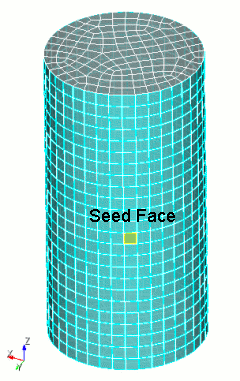
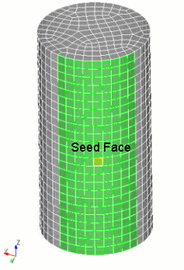
Figure 4. Grouping faces on free meshes using the seed method. The feature angle method is used on the left with a feature angle of 45 degrees. On the right is the result if using the divergence method.
Even though boundary conditions can be defined directly only on geometry entities, these geometry-based BCs will be maintained on the free mesh following the disassociate command. The following command line sequence illustrates this capability.
##Respecting blocks, nodesets and sidesets in mesh
elements after disassociation
brick x 10
mesh vol 1
sideset 1 surface 1
nodeset 1 curve 1
block 1 volume 1
disassociate mesh from volume 1
draw sideset 1
draw nodeset 1
draw block 1
Skinning a free mesh
The skin command takes a list of mesh elements and returns the triangles and faces on the boundary of that group. The group of elements returned from the command can be assigned to either a group, sideset, or block. Free meshes can be skinned by specifying either a list of hexahedra, a list of tetrahedra, or a list of blocks.
Deleting free mesh elements
Typically meshes are deleted by specifying owning geometry. For free meshes, the meshes cannot be deleted in this fashion. Instead, the mesh may be deleted using the Delete mesh command. The syntax is:
Delete Mesh
This command will delete all mesh entities in the entire model. To specify groups of elements for deletion, you can use the individual deletion commands. The command to delete a group of free mesh elements is:
Delete {Node|Hex|Tet|Face|Tri} <id_range> [No_propagate]
When deleting elements, the default behavior will be that the child mesh entities will be deleted when they become orphaned. For example, when a hex is deleted, if its faces, edges and vertices are no longer used by adjacent hex elements, then they will also be deleted. The no_propagate option will leave any child mesh entities regardless if they become orphaned.
Bottom-up element creation
Bottom-up mesh element creation methods are available for free meshes. The difference between element creation methods for free meshes versus associated meshes is that the free meshes commands do not have a command option to associate the elements with an owning body. Otherwise the commands are identical to mesh element creation commands for associated meshes. The command syntax for free meshes is:
Create Node <x> <y> <z>
Create {Hex|Tet|Tri|Face|Edge} Node <id_range>
Exporting free meshes
Free meshes can be exported as ExodusII files. All elements belonging to any block are exported. Any elements not belonging to a block will not be exported (i.e. Cubit will not assign default blocks).