Geometry Adaptive Sizing Function (Skeleton Sizing)
The Geometry Adaptive Sizing Function, also referred to as the Skeleton Sizing Function (Quadros 2005; Quadros 2004; Quadros 2004(2)), automatically generates a mesh sizing function based upon geometric properties of the model. This sizing scheme attempts to create a sizing function that allows unstructured meshing schemes to generate a mesh with the following properties:
- The sizes of the mesh elements vary smoothly throughout the mesh
- The mesh elements resolve the geometry to a sufficient degree
- The mesh elements do not over-resolve the geometry.
The geometry adaptive sizing function can be used to create sizing information for surfaces, solids, and assemblies.
This sizing function uses geometric properties to influence mesh size. The scheme calculates or estimates:
- 3D-proximity (thickness though the volume)
- 2D-proximity (thickness across a surface)
- 1D-proximity (curve length)
- Surface curvature
- Curve curvature.
These properties are then used to calculate a sizing function throughout the geometric entity (or entities). Regions of relatively high complexity will have a fine mesh size, while regions of relatively low complexity will have a coarse mesh size. For example, generally, a high-curvature region on a surface will have a finer mesh size than a low-curvature region on that surface
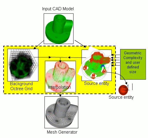
Figure 1: Overview of Computational Framework
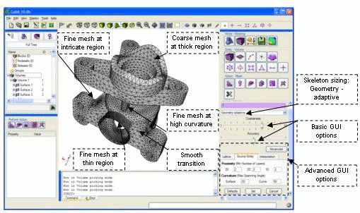
Figure 2: Skeleton Sizing Function example in the GUI
Skeleton Sizing Behaviors
Skeleton sizing can be specified on single or multiple surface(s)/volume(s) at a time from the GUI (Meshing Control Panel) or the command-line. The following describes how specifying sizing on entities can change skeleton sizing’s behavior:
Single surfaces/volumes – If skeleton sizing is applied to surfaces/volumes one at a time, each entity’s sizing is not influenced by the others. On the command-line, issue a separate command for each entity. In the GUI, specify only one surface or volume before selecting “Apply Size”.
Multiple surfaces – If skeleton sizing is applied on multiple surfaces together, then geometric features of a particular surface may affect its neighboring surfaces.
Multiple volumes (assembly sizing) – Skeleton sizing can be applied to assembly models so that geometric features of a volume may influence its neighbors. Volumes should first be imprinted and merged before they are specified together for skeleton sizing.
Command Line Syntax
Skeleton sizing on surfaces:
Surface <surface_id_range> Sizing Function Skeleton
{[scale <1 to 10 = 7>] [time_accuracy_level <1 to 3 = 2>]
[min_depth <3 to 8 = 5>] [max_depth <4 to 9 = 7>] [facet_extract_ang <1 to 30 = 10>]
[min_num_layers_2d < 1 to N = 1>] [min_num_layers_1d < 1 to N = 1>]
[max_span_ang_surf <5.0 to 75.0 = 45.0 degrees>]
[max_span_ang_curve <5.0 to 75.0 = 45.0 degrees>]
[min_size <float>] [max_size <float>] [max_gradient <float=1.5>]}
Skeleton sizing on volumes:
Volume <range> Sizing Function Skeleton
{[scale <1 to 10 = 7>] [time_accuracy_level <1 to 3 = 2>]
[min_depth <3 to 8 = 5>] [max_depth <4 to 9 = 7>] [facet_extract_ang <1 to 30 = 10>]
[min_num_layers_3d < 1 to N = 1>] [min_num_layers_2d < 1 to N = 1>]
[min_num_layers_1d < 1 to N = 1>]
[max_span_ang_surf <5.0 to 75.0 = 45.0 degrees>]
[max_span_ang_curve <5.0 to 75.0 = 45.0 degrees>]
[min_size <float>] [max_size <float>] [max_gradient <float=1.5>]}
The options are explained below:
Basic Arguments
- max_size (default=auto): The value for max_size is calculated automatically by default. Users can specify any positive real number based on the dimensions of the model to control the max size of the elements. If the skeleton sizing function creates large elements, than this argument can be used to control the maximum element size.
- min_size(default=auto): The value for min_size is calculated automatically by default. Users can specify any positive real number based on dimension of the model to specify the minimum size of the elements.
- max_gradient (1.0 to 3.0, default 1.5): The transition in element size is controlled using this parameter. Larger values of max_gradient result in fewer elements, but also lead to more abrupt transitions in size and possibly poorer quality elements.
Scaling and Accuracy Arguments:
- scale (1 to 10, default 7): The overall size of the elements is controlled by this argument. A coarser mesh can be generated by increasing the value of scale up to 10.0. To get a finer mesh, decrease the value of the scale (minimum value = 1).
- time_accuracy_level (1 to 3, default 2): This controls the computational time and accuracy level by adjusting various internal parameters of the skeleton sizing function. Users should try levels in increasing order. Level 1 takes the shortest time to compute the skeleton sizing function and Level 3 takes the longest time to compute the skeleton sizing function. However, Level 1 is less accurate than Level 2 and Level 3.
Advanced Arguments
Lattice Arguments:
The skeleton sizing function is generated and stored on a background octree grid whose cells are subdivided based on the graphics facets of the model. The level of subdivision of the background grid affects how well the sizing function captures the geometric complexity of features. Reasonable defaults have been selected for the following two refinement (subdivision) parameters, but these may be overridden for use with simple (decrease parameters) or more complex (increase parameters) models.
- min_depth (default auto): min_depth controls the maximum cell dimension of the background octree grid. The higher the value of min_depth, the smaller the dimension of the maximum-sized cell. Computational time increases with increasing min_depth. By default the min_depth is calculated based on the geometric complexity of the input model and mesh size specified on sub-entities.
- max_depth (default auto): max_depth controls the minimum cell dimension. If the object contains very fine features then increasing the value of max_depth is suggested. The maximum depth has been limited to 9. By default the max_depth is calculated based on the geometric complexity of the input model and mesh size specified on sub-entities.
- facet_extract_ang (default 10 degree): facet_extract_ang is used to control the faceted representation of NURBS model. This option gives control of the accuracy of a faceted approximation of the model used to compute the adaptive sizing. For models with high curvature regions, decreasing the tolerance will give a better approximation of the geometry and avoid the creation of random dense meshes. Note that increasing this angle too much can generate invalid facets over curved regions, while decreasing the angle too much can cause signficant slowdowns in sizing calculations.
Source Entity Arguments
- min_num_layers_3d (Any value greater than 1, default 1): This parameter ensures that a minimum specified number of layers exist across the thickness of the volume. This parameter could be useful in generating meshes for mold flow simulation.
- min_num_layers_2d (Any value greater than 1, default 1): This parameter ensures that a minimum specified number of layers exist across the thickness of a surface.
- min_num_layers_1d (Any positive integer value, default 1): This ensures that any curve contains a minimum specified number of intervals.
- max_span_ang_curve (Range 5.0 to 75.0, default 45.0): Maximum spanning angle is a parameter that controls the mesh size at curved regions of curves. It is defined as the angle subtended by the normals at the end nodes of the mesh edge in the curved region of a curve. When a finer mesh is needed at curved regions of curves, then max_span_ang_curve should be decreased.
- max_span_ang_surf (Range 5.0 to 75.0, default 45.0 deg): Maximum spanning angle is a parameter that controls the mesh size at curved regions of surfaces. It is the angle subtended by the normals at the end nodes of the mesh edge in a curved region of a surface. When a finer mesh is needed at curved regions of surfaces, then max_span_ang_surf should be decreased.
Note: These arguments override the basic arguments. For example, time accuracy level 1 internally sets min_depth = 4 and max_depth = 6, and when min_depth is set to 4 and max_depth is set to 7 in the advanced options (recommended for models with fine features), then advanced options override the basic options. In the command-line, to override the depths set by a time_accuracy_level, specify min_depth and max_depth after it.
Adding User Specified Sizing Sources
Skeleton sizing function gives an option to manually add sizing sources on geometric entiies such as vertices, curves, and surfaces. These sizing sources control the size and scope (region of influence via num_layers) at geometric entities. The below command gives the syntax for adding sizing sources. Please note that the below command for adding sizing sources should be called after issuing the above given skeleton sizing command. First, the skeleton sizing command automatically generates sizing sources based on the geometric factors such as proximity, surface curvature, curve length, etc. Issuing the below command creates sizing sources in addition to the automatically generated sizing sources. Finally, when the meshing command is called, the mesh sizing function is calculated using all the sizing sources.
Volume <vol_id_range> Sizing Function Skeleton add size_source {vertex|curve|surface} <id_range> size <double> num_layers <int>
Skeleton with Other Sizing Controls
Skeleton sizing function produces a smooth sizing function when called with other sizing controls available in Coreform Cubit. Skeleton sizing function behaves as SOFT firmness level. Skeleton sizing function always respects interval count specified on the curves. Skeleton sizing function respects interval size on curves and surfaces only if it is specified after calling the skeleton sizing function.
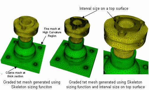
Figure 3: Skeleton sizing function with other sizing controls
Limitations
- Currently, the skeleton sizing function is primarily intended for use with ACIS models. Skeleton sizing may be used on facet-based models (STL, facet, and MBG format) models, but results are not guaranteed. Sizing function generation with other geometry engines in Coreform Cubit is not guaranteed or supported in Coreform Cubit 10.1.
- The skeleton sizing function has mainly been tested with trimesh and tetmesh schemes. In general, structured or semi-structured meshing schemes do not have enough flexibility to utilize the skeleton sizing function. It is recommended that the skeleton sizing be used only with unstructured meshing schemes. However, if using skeleton sizing in conjunction with the pave scheme for surfaces, decreasing the max_gradient and scale arguments is suggested.
- For sizing function generation of assemblies in Coreform Cubit 10.1, at least time_accuracy_level 2 is generally recommended. This helps ensure that the geometric complexity of small features is captured. For example, “volume all sizing function skeleton time_accuracy_level 2”