Command Panel Functionality
The Command Panel is arranged first by mode on the top row of buttons. Modes are arranged by task.
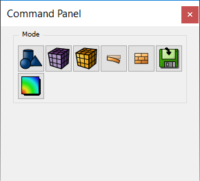
The modes are:
- Geometry
- Mesh
- Analysis Groups and Materials
- FEA Boundary Conditions
- CFD Boundary Conditions
- Analysis Setup (Export)
- Post-meshing Tool Launch
All of the geometry related tasks, for instance, can be found under the Geometry mode. When a mode is selected, a second row of buttons becomes available. The second row of buttons shown depends on the selected mode. For example, if Geometry is selected, the second row of buttons will contain operations that can be performed on geometry, such as creation, modification, decomposition, boolean, merging, deleting, and so forth.
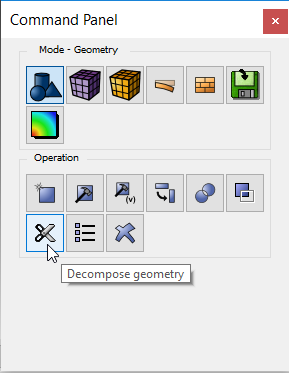
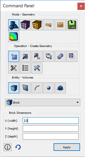
Selecting an operation will cause a row of geometry entity buttons to be displayed. Specific, entity-based operations will be shown after selecting the entity type, as shown below.
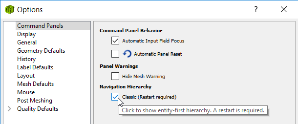
Note: This hierarchy is different than previous versions of Cubit. In previous versions the second row of buttons was geometry entity types, such as volume, surface, curve, vertex, and group. If a user wishes to use the 'classic' hierarchy for geometry, an option can be selected in Tools/Options/Command Panels.
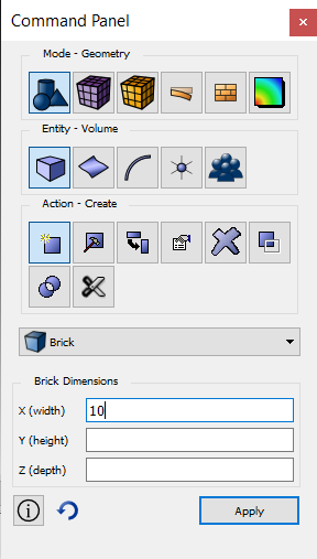
The 'classic' hierarchy's button hierarchy for creating a solid brick is the following:
For all other modes, such as mesh, analysis groups, and so forth, the 'classic' button hierarchy remains.
All command panels are constructed similarly. Each abstracts a set of Cubit commands. Options are selected using check boxes, radio buttons, combo boxes, edit fields, and other standard GUI widgets. Each command panel includes an Apply button. Pressing the Apply button will generate a command to Cubit. Nothing happens until and unless the Apply button is pressed.
Note: The edit fields are free form, which means the user may enter any valid string into the fields. Any string that is valid for the command line is valid for the command panel edit fields.
Where possible, default values are placed into edit fields. At any time, with the cursor placed over a blank portion of the command panel, the user may right-click to select Reset Data which will clear all fields and replace default values.
ID Input Entry Methods
The ID Input Fields provide a location where Geometric IDs, required for the current command, can be entered. IDs can be entered in several ways:
Simple Keyboard entry
ID numbers can be entered directly in the field. Each ID must be separated with a space. Select the field first before typing.
Graphical selection
IDs can be entered automatically by selecting entities directly in the Graphics Window. The current entity available for selection is based on the current entity selection mode. In some cases, not all entities of the current entity selection mode will be available for picking. The program may automatically filter the applicable entities based on the context of the current command
Geometry Tree selection
IDs may be entered by selecting the corresponding geometric entity from the geometry tree. To select multiple entities use the <ctrl> key.
Ranges
A range of IDs may be typed into the field. For example:
1 to 5
will automatically enter all IDs from 1 to 5 inclusive in the field. Keywords such as all and except can also be used. Any range that can be entered directly on a CUBIT command line can also be used in the ID input field. See Command Line Entity Specification for a description of the syntax.
As Part of Other Entities
Syntax can be entered in the ID Input field that will specify an entity based upon its topological relationship to other entities For example, if a Vertex Selection Type Button was highlighted, entering
in surf 1
will automatically enter all vertices in surface 1 into the Input Field. CUBIT has a rich set of syntax rules for specifying entities based upon topology relationships. See Command Line Entity Specification for a description.
In Groups
Entities that are part of groups may be specified in the ID Input Field. For example, if the Vertex Selection Type Button is highlighted, entering:
in picked
will automatically enter all vertices in the picked group into the active ID Input Field.
Dragged and Dropped
Entities can be dragged and dropped into the ID Input Field from the Tree View window.
Right-Click Context Menu for ID Input Fields
When the right mouse button is selected while in an ID Input Field, the following menu options will appear:
- Done Selecting - Enters current selection and removes cursor from selection window
- Select Other - Displays selection dialog
- Select All - Selects all available entities and puts "select all" in input window
- Highlight - Highlight the current selection
- Zoom To - Zooms to current entity in the selection field within the graphics window
- Rotate About - Change center of rotation to the center of selected entity
- Draw - Draws the entities listed in the input field within the graphics window
- Isolate - Turns visibility off for all entities other than the selected entities. Similar to draw command, but entities remain hidden with a graphics refresh. Select All Visible in the graphics window to turn visibility back on.
- Visibility Off - Removes the current entity from the input window and hides it on the graphics screen
- Mesh - Mesh the listed entities using either an assigned scheme or a default scheme where none is assigned
- Delete Mesh - Deletes mesh on all entities listed in the input window
- Reset Entity - rehighlights the entities listed in the input field within the graphics window
- List Info - Displays a sub menu of choices including basic, geometry, and mesh. Selecting the basic option will list schemes, visibility, and interval assignments. The geometry option will add information about the geometry and geometry engine. The mesh option will list information about mesh entities.
- Delete - Deletes the current geometric object in the input window.
Value Fields
Integer and real values pertinent to the command are entered in this window. Input placed in parenthesis { } will be evaluated when the command is executed. For example:
{10*0.02}
is valid input. Additionally, any APREPRO syntax is valid in the Value Field, including mathematical functions and boolean operations. See the section, APREPRO for a description of syntax.
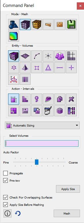
Advancing Pickwidgets
Some command panels have several id input fields such as the Mesh>Hex>Create panel. A convenience feature implemented for such panels is an advancing pickwidget feature. Pressing the middle mouse button after selecting an entity will advance to the next id input field.