Boundary Layer Meshing
Boundary layer meshing is best accessed via the GUI.
To create a boundary layer:
- On the Command Panel, click on Mesh and then Boundary Layer.
- Click on the Create action button.
- Select System Assigned ID or manually enter an ID.
- On the Settings tab, enter the appropriate size for the first row in the boundary layer.
- Enter a value for the Growth Factor.
- Specify the Number of Layer.
- Optionally select Internal Continuity.
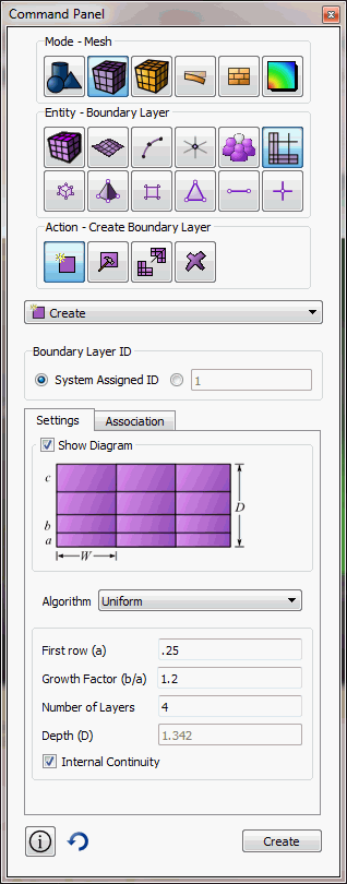
Figure 1 - Settings Panel
First row(a) -- the height of the first layer in the boundary layer
Growth Factor(b/a) -- the factor by which each layer grows
Number of Layers -- the number of layers that make up a boundary layer
Internal Continuity -- continuity flag for boundary layers. If on, all intersections are a side type.
- On the Association tab, select Curve for 2D
boundary layers or Surface for 3D boundary layers.
For 2D boundary layers:
- In the Curve ID(s) field, enter the curve ID(s) where the boundary layer(s) begins.
- In the Surface ID field, enter the surface ID that contains the boundary layer(s).
- Click Add to add the curves to the boundary layer(s).
- Click Create to create the boundary layer(s).
For 3D boundary layers:
- In the Surface ID(s) field, enter the surface ID(s) where the boundary layer(s) begins.
- In the Volume ID field, enter the volume ID that contains the boundary layer(s).
- Click Add to add the curves to the boundary layer(s).
- Click Create to create the boundary layer(s).
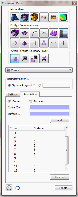
Figure 2 - Association Panel
For 2d boundary layers, a curve/surface pair is given to create a boundary layer starting from a curve and growing out on the given surface.
For 3d boundary layers, a surface/volume pair is given to create a boundary layer starting from a surface and growing out on the given volume.
Intersection Types
In some cases, the user may want to adjust the intersection types. This could be because the automatic intersection type is not desired, or because it is not workable due to ambiguity.
The four intersection types are:
- end - suitable for angles between 0 and 135 degrees.
- side - suitable for angles between 135 and 225
- corner - suitable for angles between 225 and 315
- reversal - suitable for angles 315 to 360
These intersection types may be set on a vertex/surface basis and on a curve/volume basis.
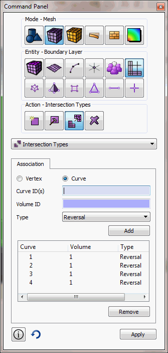
Figure 3 - Intersections Type Panel
Current Limitations
Not all combinations of intersection types and topology are supported for 3d cases. An end, corner, or reversal may not span multiple curves in a single volume. A possible workaround is to composite the curves to make a single curve.
Not all meshing schemes may be used in combination with boundary layers. In cases where it is not supported, the boundary layer will be ignored in mesh generation. It is supported with the following schemes:
- trimesh
- pave
- map
- submap
- sweep
- tetmesh.
Underlying Cubit Commands
Create Boundary_layer <id>
Delete Boundary_layer <id>
Modify Boundary_layer <id> add Curve <id_range> Surface <id>
Modify Boundary_layer <id> remove Curve <id_range> Surface <id>
Modify Boundary_layer <id> add Surface <id_range> Volume <id>
Modify Boundary_layer <id> remove Surface <id_range> Volume <id>
"*** Only three of the four parameters should be specified ***
"*** (Height, Growth, Layer, or Depth) ***
Modify Boundary_layer <id> uniform Height <double> Growth <double> Layers <double> Depth <double>
Modify Boundary_layer <id> continuity {yes | no}
set boundary_layer intersection volume <id> curve <ids> type {end, side, corner, reversal, default}
set boundary_layer intersection surface <id> vertex <ids> type {end, side, corner, reversal, default}
Boundary_layer visibility {on|off}
[set] Boundary_layer <color>
The boundary_layer visibility command toggles the
display of boundary layers in the graphics window. The [set]
boundary_layer <color> command sets the color used to
draw all boundary layers; <color> is any of
the recognized Cubit color names.
Sample Journal Files
Example 1
reset
create surface rectangle width 10 height 3
create surface circle radius 5 zplane
surf 2 move z -10
create volume loft surface 1 2
delete surf 1 2
create boundary_layer 1
modify boundary_layer 1 uniform height 0.1 growth 1.2 layers 4
modify boundary_layer 1 add surface 4 volume 3 surface 5 volume 3 surface 6 volume 3 surface 7 volume 3
set boundary_layer intersection volume 3 curve 10 type side
set boundary_layer intersection volume 3 curve 12 type side
set boundary_layer intersection volume 3 curve 14 type side
set boundary_layer intersection volume 3 curve 16 type side
mesh vol 3
Example 2
reset
create surface rectangle width 2
cylinder radius 0.1 z 0.1
cylinder radius 0.02 z 0.1
section volume 2 xplane reverse
section volume 3 xplane
volume 3 move x 0.5
create volume loft surface 12 8
unite volume 2 3 4
volume 2 copy
volume 5 scale 0.3 0.3 1
volume 5 rotate -10 about z
volume 5 move x 0.55 y -0.1
volume 2 5 move x -0.25
imprint all
delete vol 2 5
surf all scheme trimesh
group "profile" add curve in surface 30 29
create boundary_layer 1
modify boundary_layer 1 uniform height 0.002 growth 1.2 layers 6
modify boundary_layer 1 add curve in group with name "profile" surface 28
curve in group with name "profile" size 0.02
surface 28 size 0.3
surface 28 sizing function linear neighbor 2
mesh surface 28