![]()
Coreform Cubit 2025.8 User Documentation
![]()

Note: This feature is under development. The command to enable or disable features under development is:
Set Developer Commands {On|OFF}
Cohesive elements are used to model things like adhesive that may lose its bond. Elements in a cohesive region originally have zero volume or area, and then expand as the simulation progresses.
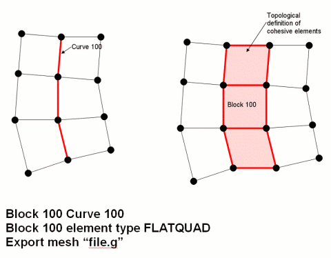
Coreform Cubit supports 2D cohesive regions. Cohesive elements are implemented in Coreform Cubit as element blocks with an element type of FLATQUAD. The cohesive region is identified by assigning geometric curves to the FLATQUAD element block. When the element block is exported, each edge on the specified curves is represented in the exported file as a 4-noded quadrilateral element with zero area. The quadrilateral element is formed by duplicating each node in the original edge and then connecting the two original and two duplicate nodes to form a zero-area quadrilateral.
The image below shows how a FLATQUAD is represented in an exported mesh file. The figure on the left is how the mesh appears in Coreform Cubit. The figure on the right is how the mesh appears in the output file. Note that the figure on the right is a topological representation, not a true geometric representation. In reality, the nodes on the left side of block 100 are coincident with the nodes on the right side of block 100, causing the pink elements to have zero area.

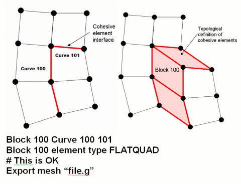
Multiple curves may be assigned to a single FLATQUAD element block, as long as the curves do not form a branching path. The figure below, for example, shows an acceptable configuration of multiple curves.

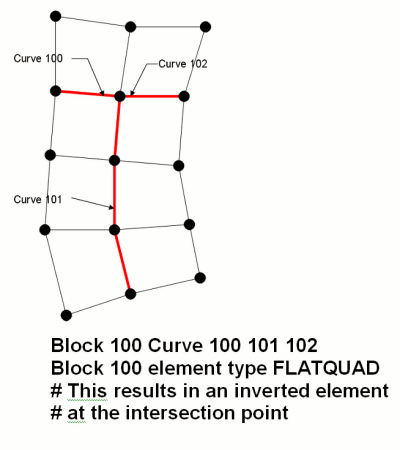
Although multiple curves may be assigned to a single cohesive block, the curves assigned to a block of type FLATQUAD must not branch. A branch occurs whenever three or more curves share a common vertex, as shown in the figure below.
